SOLVED I was on a roll... :( ... General Tso

SteveF

Member
I was doing so well. Guardian, Paragon and Paragon Mini, Pyrocumulus, all working perfectly, barring a minor shorting issue when boxing my Paragon Mini, but General Tso is misbehaving.

Sound bypassing no problem. No effect when engaged. LED comes on, Dry signal still comes through. When in blend mode, the dry signal is off with the balance pot at full CCW and 100% at CW as it should be, but no wet signal. When in “Juicy” mode, the signal is just dry, same as bypass. Treble control has no effect as far as I can tell and nor does the sustain.

Unfortunately, these things always happen to me when I have tested my wife’s patience to the point where I am summoned away from the bench, so I will update with pics tomorrow. Very frustrating. I was looking forward to this one. Any ideas off the bat based on the symptoms?
 
Last edited:
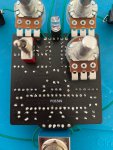
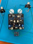
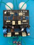
IMG_1497.jpeg IMG_1495.jpeg IMG_1496.jpeg

I've reflowed the solder on the few joints I could see where they looked like they could be dodgy, double checked the transistors are the correct ones and I've swapped out the op amp. No change. I've also cleaned off the flux. Shame on me.

I wouldn't normally have wired in the switch yet but it's a buffered bypass so wired differently to usual and I wasn't sure how to use that with my test box. I'm fairly confident the switching is working as it should. I'd have used a DPDT but didn't have one.

Any assistance appreciated.
 
shot it the dark and you probably double checked but is your LEDs on the LDR correct polarity? IE can you tell they are "lighting" inside the shrink wrap?
 
From what I can see in the pic, I don't see anything in the wrong place or oriented incorrectly... POSSIBLY a cold solder joint on the 2nd Transistor from the left (from the right on the underside pic... center conductor).
 
Id touch up that solder joint backside of pcb, right below the right side pot as seen on the pic....looks like it needs more solder (transistor as mentioned above I think).
Ive also had past issues with transistors not making good contact or being loose in those transistor sockets, I usually just solder the middle leg these days.....Good luck, hope you get it going.
 
Last edited:
shot it the dark and you probably double checked but is your LEDs on the LDR correct polarity? IE can you tell they are "lighting" inside the shrink wrap?

I double checked I put the correct leg in each hole, but haven’t actually confirmed that the LEDs are lit. I did wonder about those - presumably it compresses when they light up and all of the controls except blend only affect the wet signal? If they weren’t lighting or the LDR wasn’t going low enough resistance would that cause the symptoms I’m getting? If it is that, I would think it was the former as it’s not having any effect at all and if the LDR wasn’t going low enough I would still expect to hear something but in a reduced range?

I might cut off the shrink later and see what’s going on in there. I bought the LDRs based off the code in the BOM but maybe they’re not right - what should the dark/light resistances be?
 
uced range?

I might cut off the shrink later and see what’s going on in there. I bought the LDRs based off the code in the BOM but maybe they’re not right - what should the dark/light resistances be?

Some info on that in this thread

 
"When in blend mode, the dry signal is off with the balance pot at full CCW and 100% at CW as it should be, but no wet signal."

In BLEND mode, the signal should by 100% dry when BALANCE is full CCW and 100% wet at full CW.

"When in Juicy mode, the signal is just dry, same as bypass. Treble control has no effect as far as I can tell and nor does the sustain."

In JUICY mode, you should get only wet signal and the BALANCE pot is a volume control.

I think you have the modes mixed up in your description. The fact that the Wet and Dry signals sound the same tells me that IC1.1 is running at or near unity gain. I would still expect the TREBLE control to cut some of the treble at full CCW. Make sure you have a good solder joint on pin 2 of the TREBLE control. I see a big blob of solder there, but cannot tell if it is wicking to the pad. N.B. the hardest pads to solder are the ground pads because the ground plane draws heat away from the joint.

With power on and no signal, measure and report these two voltages:
Q3-E (pin 3)
Q5-E (pin 3)

Since we cannot read the transistor part numbers in your photos, verify that Q2 & Q5 are BC549C, Q3 & Q4 are BC557B.
 
Hi Chuck, thanks so much for your help. Entirely possible that I had the modes mixed up! :LOL:

All the transistors are the correct parts. From L-R on the board with components facing up, they are BC557B, BC549C, J113, BC557B, BC549C

I’m getting 7.3V at Q3-E and 1.35V at Q5-E.

I’m pretty sure the joint at pin 2 of Treble is ok - getting 0 ohms between that and the -ve connection point to the battery.

I definitely wasn’t hearing any difference when rotating the treble control in either mode. Same with sustain. Nothing at all.

I could be on the wrong track, but it all suggests to me that nothing is compressing. I assume the treble only affects the compressed signal? That led me to believe that the LED/LDR thing wasn’t working properly?
 
With no signal, there should be no light on the LDRs. The circuit is behaving like there is light on the LDRs. One more check of the LED drivers:

Measure the voltage across R23. Then measure the voltage across R25. Those voltages should be very close to zero.
 
OK, good, the LED drivers are off. I take it you used the most sensitive scale (200mV on most DMMs). Have you done any of your testing with the board in the box and the box closed up? That blue heatshrink may not be all that opaque. With the power off and IC1 out of the socket, set SUSTAIN to max and measure the resistance from pin 1 to pin 3 of the SUSTAIN pot. Then measure the resistance from IC1 pin 2 to the top end of R11.
 
Hey, yes. It has an auto range, but I checked and it was using the mV range. Yeah, I've tested fully boxed. (Ashamed to say I got cocky and boxed before I rocked on this one! :eek:)

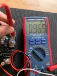
Sustain pins 1-3 measuring 0.965k

9.97k from IC1 pin2 to top of R11.
 
Ooooooh, auto-range! Fan-see.
SUSTAIN should read over 50K, close to 100K if the LDRs are in total darkness. R12 is connected, so that part of the circuit is good. We can't tell from the photos if you installed the right pot for SUSTAIN. Are you sure it's A100K? Also re-check you meter and make sure it read 0.965K and not 0.965M. It's looking like the LDRs are the problem. Do you have any more you can test?

Don't feel bad about running your first test with the board in the box. These pedals that use LDRs are best tested in a closed box so we can be sure no stray light is getting on the LDRs.
 
Sustain pot is 100k - although it's a B100k. Not that the taper matters in this instance.

Yep defo 0.965K, not M. I double checked and also wrapped the whole board in a thick cloth to ensure it's dark and got the same reading.

Yeah, I have some more of the LDRs. I'll dig them out. Presumably you want dark resistances and light?

E0E588CE-84EA-4AA9-B8CC-0904D01D8844.jpeg
 
Back
Top