BuddytheReow
Moderator

Can’t wait to see your creation!
Last edited:


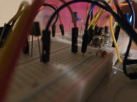
Yes, all other values are stock. At one point I had the resistors pairs each on a pot so I tried playing with values, but I finally kept the values for the base. I'm not too familiar but I guess that's a voltage divider ? I don't understand what I'm doing enough to play with that, I don't want to make the circuit unstable.Nice! Is this a stock Boost circuit minus the tweaked parallel resistor values for the emitter?
I finally kept the values for the base. I'm not too familiar but I guess that's a voltage divider
There is a difference yes, I would need to wire a switch, right now I just undo the ground side of R4 and R5 with my big fingers ... causing a lot of noise in the process so it's hard to say how much of a difference it does. My guess is that even little difference here might do a bigger difference when you add the muff part after this circuit. I'll definitely need to add a switch, I think I have a submini with pins lying around that I intend to use on a boneyard bd-2 built that I'm half into.Shot in the dark here, but R2, R3, and R4 together work as a voltage divider. When the switch is engaged, R2 and R4 are parallel (new resistance value 50K to ground) to bias the base. With the switch disengaged its just 100k (R2). Is there a big difference sonically to you for the switch?


As soon as I saw "Cliche" my brain thought it said "Kliche" and I thought it was a Klon.ALRIGHT ya hosers
So the *REDACTED* gets its own special name, subculture, kloners, religion, but y'know, there's more to life than simply eating white-as chicken breast in the pedal world. Have you considered…?


Inspired by the pork ad campaign that went on from 1990 to whenever I stopped watching TV, here it is, another one we love tohatehave mannered, civilized discussions about.
Had an extra board sitting around, and after this concept came into my brain, it was a no…brainer. Opted to use the BAT54S mini board idea by @jubal81 which ads a resistor...
- jessenator
- Replies: 11
- Forum: Build Reports
Fair enough... I might try to go further, if I have the time. Point was more to motivate the troops than to actually participate.@Nic with your circuit as is I don't think it counts as a circuit design entry, but it's nice to see people breadboarding things.
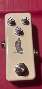
Not worthy of a full roasting unfortunately, as it’s actually a pretty tidy build. Points off for the outie jack and running your jack wires over the board. Also you’re heat shrink game…ALRIGHT ya hosers
Gimme the hate!
So the *REDACTED* gets its own special name, subculture, kloners, religion, but y'know, there's more to life than simply eating white-as chicken breast in the pedal world. Have you considered…?
Inspired by the pork ad campaign that went on from 1990 to whenever I stopped watching TV, here it is, another one we love tohatehave mannered, civilized discussions about.
Had an extra board sitting around, and after this concept came into my brain, it was a no…brainer. Opted to use the BAT54S mini board idea by @jubal81 which ads a resistor...
- jessenator
- Replies: 11
- Forum: Build Reports

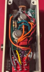
How @jessenator wires LEDs:ALRIGHT ya hosers
Gimme the hate!
So the *REDACTED* gets its own special name, subculture, kloners, religion, but y'know, there's more to life than simply eating white-as chicken breast in the pedal world. Have you considered…?
Inspired by the pork ad campaign that went on from 1990 to whenever I stopped watching TV, here it is, another one we love tohatehave mannered, civilized discussions about.
Had an extra board sitting around, and after this concept came into my brain, it was a no…brainer. Opted to use the BAT54S mini board idea by @jubal81 which ads a resistor...
- jessenator
- Replies: 11
- Forum: Build Reports

I am heat shrink game? Clearly not, given my signature move:you’re heat shrink game
Damn it! Fair enough.I am heat shrink game? Clearly not, given my signature move:

ALRIGHT ya hosers
Gimme the hate!
So the *REDACTED* gets its own special name, subculture, kloners, religion, but y'know, there's more to life than simply eating white-as chicken breast in the pedal world. Have you considered…?
Inspired by the pork ad campaign that went on from 1990 to whenever I stopped watching TV, here it is, another one we love tohatehave mannered, civilized discussions about.
Had an extra board sitting around, and after this concept came into my brain, it was a no…brainer. Opted to use the BAT54S mini board idea by @jubal81 which ads a resistor...
- jessenator
- Replies: 11
- Forum: Build Reports

Wrong thread bruh.1590A + two Ge EasyFace + on the fly perf layout. Have fun (not a true entry, but just you all can hate on it)