Garrett335
New member
Hello PedalPCB forum,
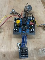
This is my first post! I have attempted to assemble a Kliche mini but I'm not getting any effect out of it when turned on.
The signal passes through when it's off, and it is very very faint when engaged.
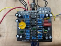
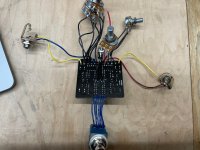
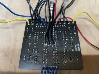
Here are some photos of the wiring etc, any trouble shooting help would be greatly appreciated!
Thank you in advance!
This is my first post! I have attempted to assemble a Kliche mini but I'm not getting any effect out of it when turned on.
The signal passes through when it's off, and it is very very faint when engaged.
Here are some photos of the wiring etc, any trouble shooting help would be greatly appreciated!
Thank you in advance!
 . I will say testing a circuit outside of the box can sometimes be disorienting. Make sure you are plugging the in jack to the guitar and the out jack to the amp. I didn’t check all the components (resistors, some caps, etc.), but learning to read color bands on resistors is pretty easy and a huge time saver when trouble shooting. My eyes are horrible though.


