Kliche overdrive problem, no sound

Uglycatstudio

New member
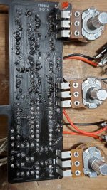
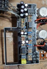
Hey everyone!! I finally took the plunge and ordered a Kliche overdrive (2 actually) to build. Followed the parts list and ordered off Tayda, spent an evening building and hit a roadblock. Led is always on, gets slightly brighter when engaging the pedal and passes no sound, on or "off". Checked all my connections and reviewed documentation numerous times. Throwing this out here as a hail mary. Any help would be much appreciated!!

Ps: used russian diodes and identification rings are reversed, although I tried reversing them with no change what so ever.
 

Attachments

  • 16381157285373770307357607772717.jpg
    16381157285373770307357607772717.jpg
    1.2 MB · Views: 71
  • 20211128_120734.jpg
    20211128_120734.jpg
    1.4 MB · Views: 73
  • Like
Reactions: fig
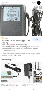
well if your using this one you have problems....
41Mt4dx6ZNL._AC_.jpg


this is what comes up when I search your Danelectro 9v 200ma supply..... what they don't tell in in the title is that it is AC not DC..... Telsa and Edison are pissed....

I know Edison fried an elephant to show the dangers of AC but you killed a Centaur

You need a 9v DC negative center power supply. if you plugged that in you fried the 1054

can you confirm your "danelectro" supply is 9VDC negative center?
Confirmed, its a vdc center negative.
I'm using a DA-1 as pictured
 

Attachments

  • Screenshot_20211207-183151_Chrome.jpg
    Screenshot_20211207-183151_Chrome.jpg
    1.2 MB · Views: 4
Last edited:
Can you confirm what Charge pump you used ie TC1044SCPA ,7660S or LT1054?
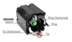
I have my concerns on the way your Jacks are wired, the Out jack looks wrong in the Picture???
Charge pump is a TC1044S and the output and input were rewired according to the diagram posted earlier (the ring was soldered to the wrong post)
 
It looks to me as if this one set up to be able to use a battery - in which case the ring of the input would usually be in use to switch the circuit on and off with insert of a lead.
 
I do agree that many of the solder joints look cold. Btw that doesn’t mean your iron doesn’t get hot enough, it means the board and component leg did not and so the solder only melted because of the hot iron. That kind of connection rarely functions as it should. Apply your iron to both the pad and the component leg for 3-4 seconds, then apply solder on the component leg, not the iron, until it starts flowing. Remove the iron.
 
It's possible that the pcb is damaged. Looking over the pics it looks like there might be signs of melting, unless its just the picture quality. I was working on a pcb a long time ago and after it was all assembled it just didn't respond properly. There ended up being a spot where under the pcb coating, the heat soldered a trace to ground. I was able to find the problem with my multimeter test point to point between components. That may be your next step, to test with a multimeter, if you know all your wiring is correct from switches, dc jack and in/out connections. But I'm still hoping it's an easy fix for you.
 
Sorry for no updates, been busy with work, family, xmas, etc. I'll provide updates later today after I clean the board with contact cleaner and reflow all the joints again.
Thanks again everyone for the help so far!!
 
Back
Top