SOLVED Lab Rat Gated on LED Setting

joelorigo

Well-known member
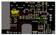
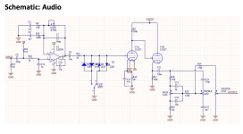
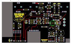
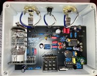
My Lab Rat is sounding gated as a note fades or is gently plucked on the LED clipping selection. It does not do it on the 1N4148 selection. Picking hard it seems normal. It did not do this previously. I don't see anything jumping out at me looking at the guts. Anyone have any suggestions on what the issue is?
 

Attachments

Last edited:
To check that I would use my DMM, checking LED pads the bottom of the PCB? And this is a high voltage circuit so I would need to be careful not to touch anything that would electrocute me, right?
 
If you can't squeeze a probe between the diode and PCB(can't tell if the are fully flush from the photo), yeah.
It would probably be present on the SI diodes as well, unless there's a solder bridge localized to the LED.
Could also check at the switch lug.
And as always , dont shock yourself. Not sure there's enough juice to electrocute but it could definitely shock the heart.
Ok thanks. As far as a solder bridge I guess I would be surprised of that since the LED setting was fine the several other times used the pedal. Sound right?

For the switch lug, I would set the switch to "LED" clipping, and measure the lug that is the opposite of the direction the switch is?

And based on your train of thought here, DC on the LEDs is bad, correct?
 
With the DMM set at “20” I get 9.25 volts at the dc jack and some voltage on the top switch lug, the SI diodes, and R12. It started at .82 and the longer the pedal stays plugged in the amount drops. After about a minute the numbers are around.38. There are 2 of the 4 LED pads that I can reach without taking it apart and they have the same reading.

After waiting another couple of minutes to type this post above, the amount has dropped below .3.
 
Sorry. I missed this.
It seems like you have some DC leakage causing offset to the clippers.
Is C8 a quality cap or a 8 cent tayda?
I'd try swapping C8 with a low ESR cap.
I could be totally off here as well.
 
No worries! Thanks for coming back!

So there shouldn't be any measured DC on those points? And why not happening on the other clipping setting?

Attaching the screenshot of the PCB to verify I am looking at C8. It is a Nichicon. I generally try to avoid the .02 cent caps from Tayda, but I have occasionally when they are out Panasonic, Nichicon or some brand i'v heard of, I've done it lol.
 

Attachments

  • Screenshot 2025-07-19 at 11.23.39 AM.png
    Screenshot 2025-07-19 at 11.23.39 AM.png
    3.1 MB · Views: 9
If it sounds fine on the Si setting and the problem is only on the LED setting, I would look at the LED themselves, make sure they are oriented correctly, and also take a look at the switch and make sure you have good connection where it's supposed to be and no connection where it's not supposed to be.
 
I will take a look at the orientation of the diodes but if ore or both were installed the wrong way, wouldn’t that have been evident when I built it last year? It was working normally before.
 
I will take a look at the orientation of the diodes but if ore or both were installed the wrong way, wouldn’t that have been evident when I built it last year? It was working normally before.
You didn't mention that, if the diodes were installed incorrectly then it would have had these symptoms from the get-go. A failed LED could be something to look at if you can measure the Vf of the LEDs.
 
Ok. To do that, I measure the DC voltage across the 2 LED's pads, which I will have do do on the bottom of thePCB since they are basically flush with the board?

And just to add some more information, when I plug it in, and when I press the footswitch, the lower LED flashes on quickly, but the upper one doesn't. Is that normal?
To measure the Vf of the LEDs you just leave the pedal unpowered and use the diode setting on your multimeter.

One LED flashing when the footswitch is pressed definitely sounds like something is up there.
 
I tried measured the LEDs. Neither of them show any reading, but the bottom one lights up when I apply the DMM prongs.
DMM is on diode setting and the screen doesn't change when the DMM prongs are touching the LED leads.
 

Attachments

  • IMG_8766.jpg
    IMG_8766.jpg
    638.9 KB · Views: 2
  • IMG_8767.jpg
    IMG_8767.jpg
    629.4 KB · Views: 2
I tried measured the LEDs. Neither of them show any reading, but the bottom one lights up when I apply the DMM prongs.
DMM is on diode setting and the screen doesn't change when the DMM prongs are touching the LED leads.
Testing either of two back-to-back clipping LEDs in circuit will not yield any definitive results. One leg of each LED needs to be lifted to test. At best while in circuit, if both are seated/oriented correctly, swapping the probes on the DMM while testing should display the same result. If one lights up while doing the test, the other one should light up when the DMM probes are reversed.
 
Back
Top