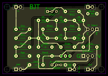
I mentioned I was developing some lazy breadboard modules in another thread and there was some interest in the idea. I'm a pretty amateur designer so feedback and suggestions are welcome. I'll publish everything on my github so people can get involved and use the modules when they're done.
I love tinkering and designing circuits but laying out breadboards for certain things is a bit of a buzz kill for me. My idea was, what if the circuit nets were already connected in the right way and all you had to do was plug in the correct components? Because you can't cover all bases on a single PCB, I think you would still need a bread board to circuit components in between modules. As such I was thinking of designing them in such a way that they plug into a breadboard, or can just be wired in with jumper cables. I'm currently at the schematic capture stage.
All the component slots will be populated by sockets, my plan is to use these socket pins, but traditional headers will work as I'm sticking to the 2.54mm spacings.
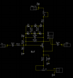
Here are the schematics as the currently exist, in my current config certain components will need to be jumpered with bus wire, or 0ohm resistors, others can simply be omitted, depending what type of circuit you wish to build.
One thing you'll notice is no Vref, that's because I favour +/- supply when it comes to OP-Amps.
I don't think this system is beginner friendly necessarily, I would say I'm targeting people like myself, intermediate and up. You have to understand how the circuits work to know what to link and omit, but that affords the most versatility.


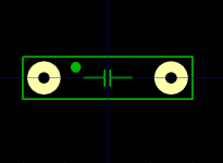
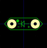
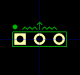
Here are the patterns I've "developed". They're designed to make identification easy, and allow for polarised components where needed.


I love tinkering and designing circuits but laying out breadboards for certain things is a bit of a buzz kill for me. My idea was, what if the circuit nets were already connected in the right way and all you had to do was plug in the correct components? Because you can't cover all bases on a single PCB, I think you would still need a bread board to circuit components in between modules. As such I was thinking of designing them in such a way that they plug into a breadboard, or can just be wired in with jumper cables. I'm currently at the schematic capture stage.
All the component slots will be populated by sockets, my plan is to use these socket pins, but traditional headers will work as I'm sticking to the 2.54mm spacings.
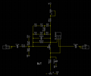
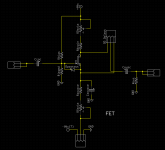
Here are the schematics as the currently exist, in my current config certain components will need to be jumpered with bus wire, or 0ohm resistors, others can simply be omitted, depending what type of circuit you wish to build.
One thing you'll notice is no Vref, that's because I favour +/- supply when it comes to OP-Amps.
I don't think this system is beginner friendly necessarily, I would say I'm targeting people like myself, intermediate and up. You have to understand how the circuits work to know what to link and omit, but that affords the most versatility.

Here are the patterns I've "developed". They're designed to make identification easy, and allow for polarised components where needed.
