Lost signal path on hylian fuzz

Joshhr

Active member
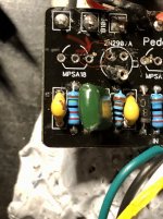
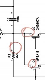
My signal goes to the first node of R2 (2m2 resistor) and there is no wave at the other end. The resistor is fine. The signal also stops at the places circled in the schematic attached. I’m wondering if it has to do this a scratch on the board (see attached image). Any thoughts and can it be fixed? Any help would be amazing!
 

Attachments

  • 99D88823-4B33-4FD5-A629-19C08E5F2618.jpeg
    99D88823-4B33-4FD5-A629-19C08E5F2618.jpeg
    651.6 KB · Views: 17
  • 66C36B4F-E72F-4BED-AC0B-4610C5187AC5.jpeg
    66C36B4F-E72F-4BED-AC0B-4610C5187AC5.jpeg
    40.5 KB · Views: 17
I read in another post that you can cover a scratch with nail lacquer. Is this true and any type? Do I apply before or after soldering?
That scratch is Ground Plane, Dont worry about it, Black ink pen!
Can you Test for Continuity on the matching Colour circles
If no Continuity between 2 points, damaged Trace ie Blue 3 to 3
Green is Ground, you can test Green circle to Scratch for continuity also:

Hylian Continuity Test.jpg
 
That scratch is Ground Plane, Dont worry about it, Black ink pen!
Can you Test for Continuity on the matching Colour circles
If no Continuity between 2 points, damaged Trace ie Blue 3 to 3
Green is Ground, you can test Green circle to Scratch for continuity also:

View attachment 12237
The only nodes that don’t have continuity are the front side of the blue circle on 2n2907 (back works) and green/ ground on 2n2907. The scratch has continuity with ground. Thanks for helping on this.
 
You say "The signal also stops at the places circled in the schematic attached." How are you observing the signal?

I would not be worried about the scratches, I'd be worried about those bodged pads. If you don't mind me asking, what the Hell happened there?

Can you measure some DC voltages?
Q1-C
Q3-C
Q4-C
Q5-C
1. I’ve been using a oscilloscope by friend lent me. I just figured out my continuity setting on my multimeter so that’s exciting.

2. lol. The great wik disaster of 2021 happened.

3. I’m quite the beginner on electronics. Hopefully I measured right. I have power going through the circuit. I grounded my black probe from multimeter. I probed the 2nd and third pads. See attached for the setting on my multimeter. My readings are:

Q1: 2: .52 and 3: .6
Q3: 2: .17 and 3: .23
Q4: 2: .17 and 3: .23
Q5: 2: 0 and 3: .23
 

Attachments

  • A93DF94A-1E75-4DDF-B515-286C22CCC389.jpeg
    A93DF94A-1E75-4DDF-B515-286C22CCC389.jpeg
    1,020.1 KB · Views: 0
You've got at least one broken pad or trace, maybe more. You might want to chalk this one up to experience and start over with a fresh board. Were these measurements taken with all transistors installed? The collector voltage readings seem low to me, but this is a crazy pedal and all things are possible. Don't bother measuring voltage on the base, the circuit resistances are too high and your meter will will load the circuit down.
 
The only nodes that don’t have continuity are the front side of the blue circle on 2n2907 (back works) and green/ ground on 2n2907. The scratch has continuity with ground. Thanks for helping on this.
I want to see the rest of the PCB Board & I will give my decision, but I'm leaning towards Chuck's suggestion.
 
It's a learning experience. Lotta folks are all to quick to start pulling parts off when they're troubleshooting. Bad move because pulling parts can do more harm than good and unless you get lucky, you won't find the problem.
 
It's a learning experience. Lotta folks are all to quick to start pulling parts off when they're troubleshooting. Bad move because pulling parts can do more harm than good and unless you get lucky, you won't find the problem.
Good call. I really appreciate your help. I’ve built a bunch and left my troubleshooting to now. I’m working on troubleshooting the rat clone now. The sound is super quiet.
 
Back
Top