Muffin fuzz quit working

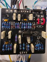
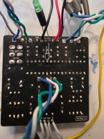
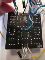
Have a muffin fuzz, green russian version, that I built a few months back. Worked well but then stopped working. Looking for some advice on where to start. I've reflowed everything and have started chasing voltages. Any thoughts would be appreciated. Think I am too close to it and frustrated 🥴
 

Attachments

  • 20260602_165843.jpg
    20260602_165843.jpg
    492.9 KB · Views: 19
  • 20260602_165905.jpg
    20260602_165905.jpg
    382.8 KB · Views: 19
  • 20260602_165913.jpg
    20260602_165913.jpg
    411.9 KB · Views: 19
Hadn't tried that yet because my test amp was down. Got it fixed and ran a test.

I get signal on the sustain pot (b100k) that is equal to my input signal (1khz square wave). Signal on the volume pot (b100k) is there but barely noticable when turned all the way up. Will send some scope pictures when I get a minute
 
My brain isn't braining and my pedal is starting to laugh at me.
I get bypass signal. When the circuit is engaged, signal cuts out. Continuity on the switch and breakout board seems to test out fine.
When I connect the breakout board to the main board and have the switch disengaged, which of the connections should I have continuity between? Which connections should I have continuity when the switch is engaged?
 
1. 4. 7
2. 5. 8
3. 6. 9

Thats your switch.

1 connects to the pcb input
2 to tip of output jack
3 is connected to 9
4 is connected to sw pad on board (led)
5 is connected to ground
6 is connected to 1
7 is connected to pcb out
8 is connected to output jack
9 is connected to 3

When “on” signal from 2 goes to 1 which enters the effect, signal from pcb out goes to 7 which is connected to 8 then to the output jack. 4 is connected to 5 giving your led ground so it turns on.

When off signal goes from 2 to 3 to 9 to 8 to the output jack, 6 slbecones grounded which grounds the pcb input.

If you have signal at lug 3 of the volume pot but none at the wiper. First I’d verify the position of your volume knob. Id turn it fully cw, at that point the two should have continuity between lug 3 and lug 2.
 
1. 4. 7
2. 5. 8
3. 6. 9

Thats your switch.

1 connects to the pcb input
2 to tip of output jack
3 is connected to 9
4 is connected to sw pad on board (led)
5 is connected to ground
6 is connected to 1
7 is connected to pcb out tunnel rush
8 is connected to output jack
9 is connected to 3

When “on” signal from 2 goes to 1 which enters the effect, signal from pcb out goes to 7 which is connected to 8 then to the output jack. 4 is connected to 5 giving your led ground so it turns on.

When off signal goes from 2 to 3 to 9 to 8 to the output jack, 6 slbecones grounded which grounds the pcb input.

If you have signal at lug 3 of the volume pot but none at the wiper. First I’d verify the position of your volume knob. Id turn it fully cw, at that point the two should have continuity between lug 3 and lug 2.
That's a really clear explanation. I'd definitely follow your advice on checking continuity between lugs 2 and 3 of the volume pot with the knob fully clockwise before assuming the pot is faulty.
 
I'm not in a position to do any more testing tonight but when I tested earlier I had continuity between lugs 2 and 3 when fully cw and continuity between lugs 1 and 2 when fully ccw.

I will run through the switch again in the morning.
 
I have continuity between lug 2 and the tip of the output jack.

Checking the switch I get the following:

1 has continuity to pcb input
2 does not have continuity to output tip but does have continuity to input tip
3 has continuity to 9
4 has continuity to sw pad
5 has continuity to ground on both jacks, dc jack, and both gnd pads on the PCB
6 has continuity to 1
7 has continuity to pcb out pad
8 has continuity to output jack both tip and sleeve
9 has continuity to 3
 
Right after posting my last comment, i happened to bump lugs 1 and 2 on the volume pot while connected to pin 5 on the switch. Turns out that all of the lugs on the volume switch are grounded. :confused:
 
Back
Top