Mentaltossflycoon
Well-known member
I guess I'm the fool for testing 
I socketed the biasing resistors in my Desolate only for the first two random J201s to work perfectly with the stock values.Yeah, I just saw the measurements in the schematic and remembered the troubles some had with the desolate j201s. I also toasted a fet on my lowtide which ended up being my first public troubleshoot.
If I can do it, surelyI socketed the biasing resistors in my Desolate only for the first two random J201s to work perfectly with the stock values.
As for the Low Tide, it's got pride of place in my Hall of Shame. Never worked properly.
I have another board for when I'm ready to give it another try.

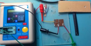
To measure Idss I use a cheap chinese T7 component tester, this is my setup:I didn't test any of the J201s that I used. I am both lazy and don't have a good way to test SMD parts. Turned out fine for me. YMMV

Where did you buy this tester? I bought a very similar one but it will not read jfetsTo measure Idss I use a cheap chinese T7 component tester, this is my setup:
View attachment 100603
It works reliably, but i need press down the transistor against the copper tape to create contact. I use that rubber thingie in the upper right of the picture for that.
I've thought about replacing the plate with a small pcb with slightly larger pads than the usual foot print for smd transistors plus test pins,
and I guess it would help if I didn't need to hold down the transistor with one hand. Maybe something 3d printed?
The tester does not get any value for Vp, Vgsoff and such, been wondering if the Id @ Vg values can be used for calculating or approximating them
Indeed, Same observation here. Seemingly that's a different (newer?) firmware. Shouldn't be a big deal to update that.Where did you buy this tester? I bought a very similar one but it will not read jfets
Indeed, Same observation here. Seemingly that's a different (newer?) firmware. Shouldn't be a big deal to update that.
This seller on AliExpress:Where did you buy this tester? I bought a very similar one but it will not read jfets
Thanks. Does it do germanium transistors too? Mine also won’t do that.This seller on AliExpress:
I have an older one too that is good but it doesn't measure JFET and has a monochrome screen. I don't know at which Vds that Idss is measured at, it's not 9V and I don't think it's 3V as in the build instructions.
I didn’t know you could update the firmware. I’ll have to look into thatIndeed, Same observation here. Seemingly that's a different (newer?) firmware. Shouldn't be a big deal to update that.
My quick search revealed a different T7 transistor tester, only. Anyway these boxes are (mostly) "implementations", respectivelyI didn’t know you could update the firmware. I’ll have to look into that
My TC1 tester reads Germanium leakage. No idea if it reads JFETs, actually.Thanks. Does it do germanium transistors too? Mine also won’t do that.
Lovely! I'm using one of those JFET breakout boards for the first time; I used spare snipped leads and soldered it to the back of the board instead of the front as you did here (because there wasnt room on the front). This is for an AionFX build. Assumed that that white strip would serve as sufficient insulation against the other joints it touches on the back of the board. Do you think thatll work?I was already a big fan of fairfield inspired circuits being a frequent user of the chopshop, lowtide, and desolate fuzz. I figured this wouldn't suck and I was quite correct. The desolate lacks a little low end, even though I greatly enjoy the sounds it makes with bass. This Nein fuzz doesn't have that issue so much, I have no hesitation saying that it's "good" for the bass players. It's also nicely versatile.
I have many fuzzes that I only enjoy with the fuzz dimed but the nein sounds good dialed all the way down into fairly clean territory. The fuzz control and the input control are interactive and you can conjure many textures for a pedal with no tone knob. When maxed out it's pretty huge but it's tame when comparing with the desolate. It kind of does everything the desolate doesn't. The bias control only adds to that versatility providing some gated tones too.
Easy building, found appropriate fets quickly though they all three came from different batches and happen to be soldered in different directions, one with pins, the others with resistor legs. Looks more chaotic than it is.
View attachment 100356View attachment 100357
I'm pretty sure the white strip is just for labeling but you should be good to solder in your leads in whatever direction you need.Lovely! I'm using one of those JFET breakout boards for the first time; I used spare snipped leads and soldered it to the back of the board instead of the front as you did here (because there wasnt room on the front). This is for an AionFX build. Assumed that that white strip would serve as sufficient insulation against the other joints it touches on the back of the board. Do you think thatll work?
