You are using an out of date browser. It may not display this or other websites correctly.
You should upgrade or use an alternative browser.
You should upgrade or use an alternative browser.
Neurocyton Preamp - Greer Soma
- Thread starter almondcity
- Start date

Flashheart
Member
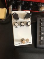
Looks great. What did you use for the lettering?
almondcity
Well-known member
I used some rubber stamps I have and StazOn ink
almondcity
Well-known member
This is a jfet overdrive type pedal with full EQ. It's quite different sounding than the Broadcast which to me has kind of a "guitar plugged straight into the console" sound and only the low cut control. All 3 are good pedals but I like this the best, the EQ is more powerful than on the Benson I think
bhcarpenter
Well-known member
That’s one hell of an endorsement! What’s your rig like?10x better than the Benson Preamp in my opinion.
almondcity
Well-known member
Admittedly just a Blues Jr at fairly low volume. Your mileage may vary
smithcircuits
New member
Building this right now and stupidly soldered in the transformer without checking the orientation. Not sure I can pull it without destroying the pads... I don't suppose it'll work backwards? Anybody got an idea?
smithcircuits
New member
Svenson007
Active member
Cool build! I’ll defiantly be ordering one next. How do you do your labels?I got lucky - It works fine with the transformer backwards. Labelled my master & gain backwards too...Terrible hobby for someone with ADHD. Sounds great though!
innerlight
Active member
Could someone talk this noob through the calibration process? Right now it’s not actually passing signal, but I’m hoping this is the issue
almondcity
Well-known member
I biased the jfets to 4.0V on the drain, if I remember correctly.Could someone talk this noob through the calibration process? Right now it’s not actually passing signal, but I’m hoping this is the issue
innerlight
Active member
Could you talk me through how to bias? Like where to place DMM probes and what setting to have it on? I'm a beginner!I biased the jfets to 4.0V on the drain, if I remember correctly.
Also is it possible that a unbiased pedal would not pass signal? My LED is on, it works in bypass, but not when engaged right now. I can hear the pentameters changing the sound also, but no signal is getting through
Thanks!
Last edited:
Quirkey
Active member
The simplest way is to clip your ground onto the pedal's ground and then the test (other side) of the DMM to the drain of the JFET. JFET leads are labeled D (Drain) S (Source) G (Gate). Search online for the pinout of the JFET you're biasing. Set the DMM to voltage measurement and then adjust the trimmer until it reads the voltage you're looking for. This is the most quoted article/reference with a lot more detail http://diy.smallbearelec.com/HowTos/BreadboardBareAss/BreadboardBareAss.htmCould you talk me through how to bias? Like where to place DMM probes and what setting to have it on? I'm a beginner!
Also is it possible that a unbiased pedal would not pass signal? My LED is on, it works in bypass, but not when engaged right now. I can hear the pentameters changing the sound also, but no signal is getting through
Thanks!
innerlight
Active member
Many thanks! Ill report back..
A while back, Mr PPCB posted that the unit he traced was calibrated to:I biased the jfets to 4.0V on the drain, if I remember correctly.
Q1 - 4.45v
Q2 - 4.3v
Q3 - 4.46v
Q4 - 4.75v
And to add to the previous advice, i usually just stick the ground probe into one of the screw holes on the chassis. Assuming everything is grounded properly, I find this to be easiest way to go. I've had clips come loose without me realizing it and then I can't figure out what the problem is until I finally notice the black probe flapping in the breeze.
Also, if your pedal works in bypass and you can hear the parameters changing the noise, you're in the ballpark. Might just be a problem w your footswitch wiring or the pcb in/out wires. Post a pic of the guts and somebody in here might be able to help.
innerlight
Active member
Thanks heaps!A while back, Mr PPCB posted that the unit he traced was calibrated to:
Q1 - 4.45v
Q2 - 4.3v
Q3 - 4.46v
Q4 - 4.75v
And to add to the previous advice, i usually just stick the ground probe into one of the screw holes on the chassis. Assuming everything is grounded properly, I find this to be easiest way to go. I've had clips come loose without me realizing it and then I can't figure out what the problem is until I finally notice the black probe flapping in the breeze.
Also, if your pedal works in bypass and you can hear the parameters changing the noise, you're in the ballpark. Might just be a problem w your footswitch wiring or the pcb in/out wires. Post a pic of the guts and somebody in here might be able to help.
I just made a separate thread to solicit advice, but basically Q2 & Q3 are both up around 8v at lowest adjustment, so I’m wondering if I’ve got a wrong part in there. There’s photos there too! Have a look if you may.
Thanks again, C