Obsidius preamp problems

When I turn on my obsidius preamp the distorted signal doesn't come through (only raw sound and some sizzle). If I flip the toggle switches a million times it will come through, but then I try to flip it to the ones I like (or again at all) it cuts out again. To get it to the setting I like and work at the same time it takes awhile. Also, when I switch the pedal off and back on it normally goes back to no distortion (only raw sound and some sizzle) coming through.
I honestly don't know where to start diagnosing this problem. I'd guess check the switches but this happens no matter which switch I flip so I honestly don't know.
 
Advice to newbies:
The vast majority of the problems we see here are due to workmanship. Help us help you by doing these things:
1) Read the other posts in this forum.
2) Clean your board with IPA & a toothbrush.
3) Perform a thorough visual inspection of all components and solder joints. Use good lighting and magnification.
3a) For examples of bad solder joints, look at the pix in this forum.
3b) For examples of good solder joints, look at the pix in the Build Reports forum.
4) Reflow / resolder only the joints that look bad. You can resolder a joint only so many times before the traces start to lift or the parts get damaged.
5) If it still doesn't work, post detailed photos here.
6) Make sure you have a DMM, even if it's one of the Harbor Freight freebies. And an audio probe.

Good luck!
 
numbering my responses to line up with yours
1, for this pedal there arent any useful posts that ive found on this forum
2,havent done that will admit, dont have an isopropyl alcohol atm
3-4 have done various times, including right after i built it as i was having these same problems initially (my other post was about this pedal and i ended up having these same issues after my initial problem where i fixed a couple solder joints), reflowed some today just in case, i also put electrical tape on the back of the blend to ensure the back of the pot doesn't short anything on large ic (there was no electrical tape at first so figured id do it just in case but doesn't seem to be changing my issue at all hope its not that)
5 alright
6 i have both but have never used an audio probe to test before
 

Attachments

  • IMG_20190927_131509456.jpg
    IMG_20190927_131509456.jpg
    838.8 KB · Views: 65
1. True, but the general flavor of the troubleshooting discussions is relevant:
a) We always ask for pix.
b) We expect those who ask for help to do their due diligence and inspect everything first; they don't always do that.
c) Workmanship is the #1 cause of a pedal not working.
d) J201s are problem parts.
2. OK
3. OK
4. OK
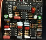
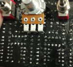
5. Thanks for the pix. Soldering on the top side looks good. Part orientations look good. Need a clearer pic of the solder side.

Apologies for inferring you were a noob. But you did do something that the noobs do: You did not include pix with your initial request for help.

One end of R19 appears to be up against C101. Make sure it hasn't breached the insulation and shorted to GND.

I think I found something. R12 should be 470K resistor, is a capacitor. To the right of the 4049, you have two caps. Should be capacitor and resistor. This may not be the only problem.

You used electrolytics for the two 1uF caps, should be film. Will probably work with electrolytics, provided you get the polarity right. C5 probably doesn't matter. C22 should have the + side closest to the edge of the board.

Lotta people have been having problems with J201s (as evidenced in this forum). Let's make sure they are happy. Check the voltage on Q1-1. Should be just above 4.5V. Check the voltage on Q1-2. Should be greater than zero.

Check the voltage on pins 1 & 7 on the TL072s. They should all be near 4.5V.
 
Yeah, I was playing catch-up as I wrote. Solder side photo is still unclear, focus not good. It is hard to get good photos with a smartphone unless it has macro capabilities (mine doesn't). I use my trusty old Canon A590 for macro shots. Not sure, but some of the solder joints might be cold.
 
Its fine with the noob thing, what I had said previously was to help give an idea of my level of noobness lol. Like, i'm a noob but I have made one perfectly working on first try build from here lol, and have been soldering for awhile, wired my guitars/pickups etc...

Ics are correct, its just the picture/lighting.
Checked the r19/c101 thing up close and its fine.
The green electrolytics are supposed to be non polarized and don't have the marking so they should be fine (they are some of the non polarized electrolytics from mammoth electronics).

Good catch on the cap that is supposed to be a resistor! I honestly don't know what made me do that, and probably explains why I was missing a cap while building one of the other pedals I was building at the time lol.
After I fix that i'll test it, and then check the voltages!
I believe I have a few backup j201 and tl072. hopefully none of those are fried cuz i'm assuming not having that resistor could cause voltage issues from that big ic.
 
Last edited:
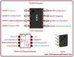
im following this, 1 and 7 im getting 0 on all now (pedal on, no playing through)
when i do 4 and 8 i get around 8 volts (using battery atm)|

fresher battery same thing except 9 instead of 8
 

Attachments

  • TL072_Pinout-1.png
    TL072_Pinout-1.png
    72.6 KB · Views: 11
Last edited:
All measurements are with respect to GND. Those JFET measurements are not exactly what I asked for, but they do show that the JFETs are working. Measure from Q1-2 to GND (Q1 is on the right). Measure TL072's from pin 1 to GND. Measure from pin 7 to GND.
 
viewing from component side
left j201
left to center 4.1
right to center .22
left to right 2.9

right j201
left to center 4.2
right to center .18
left to right 2 (do i have to max out any of the knobs while measuring?)
 
You just don't want to put the black meter lead on ground when measuring the JFETs, hmmm? Do not bother measuring pin 3 on the JFETs; the impedance is too high there and your meter loads the circuit down. The other measurements look correct. Good news is, the JFETs and opamps are biased correctly.
 
Sorry didn't think you meant do it to ground on the jfets too.
Oh btw, the toggle switches still seem to change the eq, and when the blend is to the raw signal it goes through fine, but when it's to the distorted side it barely comes through but eq is changed and it's not distorted or as loud as it's supposed to be.
I'm at work ATM so I cant test anything rn. And also after fixing the resistor I did flip the switches a good bit and the distorted signal didn't end up randomly working like it did before (maybe If I had more time to do it it would end up working), so I suppose I should check the diodes? Maybe while touching up some stuff I messed those up somehow?
 
Last edited:
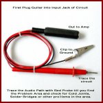
Time to start testing with the audio probe. Please post a picture of your audio probe so I can guide you on how to use it. You're basically going to plug the probe into an amp, connect one wire to ground and touch various parts of your circuit with the other wire and listen to what you get. If you have a pedal that will oscillate on it's own, like a Fuzz Factory, a delay or flanger that will oscillate when the feedback control is turned all the way up, you can use that for a signal source. Otherwise you or an assistant will have to strum a guitar to make a test signal.
 
Sounds good, I'm at work right now so I looked for a picture on Google. The picture ooks exactly like mine (got it a long time ago). I do have a delay with a built in short looper so should be good on that.
 

Attachments

  • Audio-Probe.jpg
    Audio-Probe.jpg
    188.8 KB · Views: 21
Back
Top