Ocelot voltage question and other beginner questions

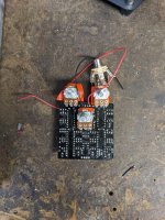
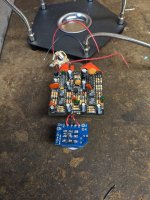
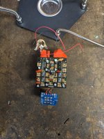
I'm building an ocelot octave and finished the board and was testing it out. The led would come on as soon as I plugged in my source but when I cycled the switch it would turn off and not come on. After thinking about it for a bit I realized I had never actually checked the input voltage for the ocelot and as this is my first build I'm struggling a bit with reading the circuit schematic that is provided in the build docs. I guess I just assumed that it was 12v and I cannot explain why. I now suspect it's actually 9v. Additionally if I had bought capacitors rated for 12v would I need to replace all of those caps with 9v rated ones? Finally I would really appreciate any feedback about other issues you see on my board except for bad solders. I'm planning on reflowing all of the connections soon so any bad connections will be fixed. Thanks for the help and not making TOO much fun of me for a dumb mistake.
 

Attachments

  • PXL_20230530_203647719.jpg
    PXL_20230530_203647719.jpg
    731.9 KB · Views: 23
  • PXL_20230530_203635407.jpg
    PXL_20230530_203635407.jpg
    581 KB · Views: 22
  • PXL_20230530_203629575.jpg
    PXL_20230530_203629575.jpg
    611.7 KB · Views: 22
Welcome! The Ocelot is a great pedal but ambitious. The voltage for the power source should be 9V. For 9V pedals, without a charge pump, I typically use 16V or 25V capacitors.

As for your pedal, I noticed a few things and have some suggestions.
1. Two transistors are soldered in the incorrect position. (Flat side matches the flat side of the depiction on the PCB)
2. I am not familiar with the IC used to substitute for the TL072. They might be equivalent, but I do not know.
3. It appears that the “in” and “out” on the board are not connected to the footswitch PCB. Without those connections, the pedal will not work.
4. Most footswitch PCBs will not need the jumper wires between the lugs. The PCB makes those connections. The importance is to correctly identify where to connect the circuit’s wires to the corresponding spots on the footswitch PCB. PedalPCB makes a footswitch board that makes it easy.
5. Most of us use sockets for our ICs. This makes it easy to remove the IC when troubleshooting or testing a different IC.

The gurus may have noticed some other issues, so hearing their thoughts might be helpful

While you are working out the bugs with this build, you could try some other great circuits with lower part counts. These circuits make it easier to learn and troubleshoot when problems arise. One of my favorites is the Chop Shop. It is a low to medium gain pedal.
Thanks for your help! I meant to put it in the original post but those transistors were put in backwards on purpose on the advice of the guy I bought them from. He could be wrong but he does run an electric supply shop. I think I'll probably do sockets for the chips. I've got a good desoldering station so it won't be that hard. Luckily I think I'll only have to replace 1 or 2 of the capacitors so that's great news to me. Thanks for noting the in and out on the switch. When I took these pics I had already started removing the footswitch bc I had made my wires a bit too long. Good to know about the jumpers when using the pcb. I'll do some work on it this weekend and hopefully come back with some good news
 
What type of transistors are they (numerical code)?

Also, problems with the LED may well be the switch - they are pretty sensitive to heat so too much time soldering can be enough to damage them. I always make sure I have spares in case.
 
What type of transistors are they (numerical code)?

Also, problems with the LED may well be the switch - they are pretty sensitive to heat so too much time soldering can be enough to damage them. I always make sure I have spares in case.
It has been a while since I built this pedal, but I think I used these transistors.

 
What type of transistors are they (numerical code)?

Also, problems with the LED may well be the switch - they are pretty sensitive to heat so too much time soldering can be enough to damage them. I always make sure I have spares in case.
The transistors are an NTE123AP luckily I got a great price on a pack of 10 switches with pcbs so I'm all set on spares.
 
Looks as if NTE123 would probably work for Q1, the same way around. It won't work for Q2 or Q3 - they are FETs whereas NTE123 is a NPN.
 
Yep, that looks better. They would probably work facing the same way (FETS are usually pretty symmetrical) but turning them backwards is technically correct.

Reading the first post it seems as if the only problem with functionality you are having is with the LED? You can think of the LED as being a completely separate circuit from the rest of the board. It is just 9V - Led - resistor - switch -ground. If the LED is misbehaving then one of those components has to be the problem. Most likely the switch. You can use a multimeter on continuity or low ohms range to measure the switch (with the power off) and make sure that the correct tabs connect/disconnect as they are supposed to.
 
Back
Top