Op Amp Big Muff not working.

farwest1

Member
I just finished up putting this in the enclosure and—bummer, it doesn’t work. I get full guitar sound in bypass, but barely any sound when engaged. Just very faint (and doesn't sound distorted.)

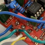
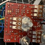
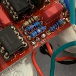
The build is actually an Aion Electronics Muff—PedalPCB version was sold out. It allows for either single or dual second stage op amp. I'm showing the TL072 as a single. That empty op amp slot would take a dual 4558 as an alternate.

In addition, it includes a modification that I didn't install, which would have included CX1.

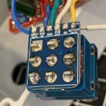
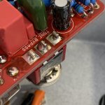
Any errors stand out to anyone? When I've made mistakes in the past, it's almost always been in the off-board wiring. Is my grounding ok? Do I need to ground the output jack?
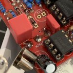
 

Attachments

  • IMG_2026.jpg
    IMG_2026.jpg
    809.3 KB · Views: 24
  • IMG_2027.jpg
    IMG_2027.jpg
    620.8 KB · Views: 25
  • IMG_2028.jpg
    IMG_2028.jpg
    855 KB · Views: 20
  • IMG_2029.jpg
    IMG_2029.jpg
    675.9 KB · Views: 22
  • Screen Shot 2020-06-25 at 5.32.57 PM.png
    Screen Shot 2020-06-25 at 5.32.57 PM.png
    313.2 KB · Views: 20
  • Screen Shot 2020-06-25 at 5.33.19 PM.png
    Screen Shot 2020-06-25 at 5.33.19 PM.png
    166.3 KB · Views: 19
Last edited:
Cool, so the board is definitely getting power.

The 3PDT mini board makes off board wiring pretty hard to screw up. The schematic looks pretty straight forward, I think your best bet is to work your way through the circuit with an audio probe and try to find where the volume drops. It sounds like you've probably got an incorrect component value somewhere.
 
Thanks Twebb and Barry. I fixed the grounding and re-soldered the volume pot. Still no luck.

I did notice that the temp on my iron was set lower than normal. But I'm bad at identifying cold solders. I'm including a few other pics here—maybe you could see if you can spot any other errors?

This is the first pedal in a while that didn't work for with a couple of corrections, so I'm a little bummed. But I also admit I got sloppy at the end. I'll build an audio probe and check for bad connections too.
 

Attachments

  • IMG_2036.jpg
    IMG_2036.jpg
    471.4 KB · Views: 12
  • IMG_2037.jpg
    IMG_2037.jpg
    620.7 KB · Views: 15
  • IMG_2038.jpg
    IMG_2038.jpg
    539.9 KB · Views: 16
  • IMG_2039.jpg
    IMG_2039.jpg
    743.5 KB · Views: 15
  • IMG_2040.jpg
    IMG_2040.jpg
    569 KB · Views: 15
  • IMG_2041.jpg
    IMG_2041.jpg
    607.5 KB · Views: 13
  • IMG_2042.jpg
    IMG_2042.jpg
    656.2 KB · Views: 12
You could get by with much less solder, more isn't always better your solder joints should look conical, anything that looks like a ball or blob should be reflowed, what temperature are soldering with?
 
You could get by with much less solder, more isn't always better your solder joints should look conical, anything that looks like a ball or blob should be reflowed, what temperature are soldering with?
Yeah, I think this was the result of the iron temp being too low. The solder wasn't flowing onto the pads quite right, so I increased the amount.

Normally the iron is around 325-350ºC. But it had dropped to about 250ºC (it has a dial on the handle that's easy to accidentally turn.)
 
Yeah, I think this was the result of the iron temp being too low. The solder wasn't flowing onto the pads quite right, so I increased the amount.

Normally the iron is around 325-350ºC. But it had dropped to about 250ºC (it has a dial on the handle that's easy to accidentally turn.)
How high will it go? I'm usually around 750 to 800F or 400 to 425C, a hotter iron gets you on off the joint quicker soldering too low can leave heat on the component for too long
 
Have you tried it out of the enclosure?
I have. No luck. I looked for any shorts from components touching the enclosure. Everything seems clear.

My best guess is that I have some cold joints, or over-soldered joints that aren't working. I just don't know how many components I soldered at the low temp—my cheapo iron has an extremely small temp dial right where you hold it. So it's hard to notice when it's not correct.
 
I've found the best way of sorting out poor solder joints is by putting a bit of flux on it and hitting it with a hot iron. This wets the solder, helps it flow where it's needed, and finishes nice and shiny.
Thanks! With a cold solder, is the solder itself ruined, or can it just be reflowed at a hotter temperature and create a solid connection?

In other words, do I have to debraid or sucker it and place new solder? Or can I basically re-flow the same solder onto the joint?
 
You can definitely just reflow, a hot iron and some flux will help a lot. As Barry said, just be careful you're not heating components for too long. Some parts are very sensitive to heat, and the board can also be damaged if you reheat too many times.

The type of solder you use also makes a difference. Lead free solder is more prone to becoming cold, I tend to find a 60/40 tin lead solder works best for me.
Thanks! Can I ask: could a few cold solder joints be the reason I'm getting barely any signal when the pedal is engaged?
 
Absolutely. If you haven't got a strong conductive connection, signal isn't going to flow as efficiently.
I re-flowed all connections. Still nothing. I guess I'll test with an audio probe, but I'll have to build one first.

Two other thoughts: did I get the ICs wrong? IC1 called for an RC4558P, I installed a 4558D. In the IC3 spot, a TL072 should work—I used a TL072CP.

And: for the switch, I think the schematic called out an on-on SPDT toggle. But I used an on-off-on SPDT toggle. Would that matter?
None of that should matter
 
Back
Top