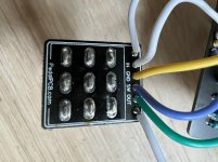
Oxide, Working then Not Working

apierz

Member
I've been running into issues with putting together an Oxide pedal. After assembling it, bypass sounded fine but when switched on the pedal was very quiet. I started checking component values with a DMM and found a number that were out of tolerance so I replaced those and the circuit seemed to be working. I checked it after each stage of the assembly (jacks mounted to case, &c.) to make sure it was working but after I got it fully assembled there was no noise when the pedal was turned on. I tried checking for shorts, swapping out the IC and transistors, and reflowing any solder joints that looked suspicious but nothing worked. Even fully out of the case I can't get any noise when the pedal is turned on.
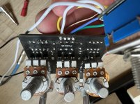
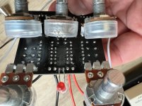
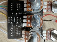
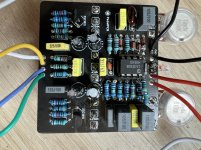
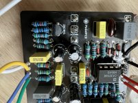
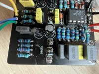
Image.jpeg Image-1.jpeg Image-2.jpeg Image-3.jpeg Image-4.jpeg Image-5.jpeg Image-6.jpeg
 
Not sure if this is useful but I tried measuring voltage across components to see if/where there was a break in the current but I get a pretty consistent reading across every component I test. Including from out to ground.

Is there a good way to work through the circuit path to see if I can track down where the problem is?
 
  • Like
Reactions: fig
I don't think you have the power wired correctly if red = + and black = - . I have not looked at a build doc, but most PedalPCB board maintain the same power orientation.

L to R = GND + A K - GND
 
I don't think you have the power wired correctly if red = + and black = - . I have not looked at a build doc, but most PedalPCB board maintain the same power orientation.
I have black for + and red for - in this one. Wire color for me is more or less random. Power doesn't seem to be the issue. The LED lights and the pedal seemed to be working for at least a few minutes before it stopped.
 
  • Like
Reactions: fig
You can rig an audio probe and follow the signal path from the schematic. I'd start with the switch connections. A search for "audio probe" will give you an idea....jack, wire, cap...boom!

Someone else may spot something or simply solve the case...but it's good to have a probe handy...
 
It kinda looks like your lead off the led is very close to the black + wire, could it have come in contact grounded and shorted?

Unfortunately, that's not it. I cleaned it up just to be sure but I still get no signal.
You can rig an audio probe and follow the signal path from the schematic. I'd start with the switch connections. A search for "audio probe" will give you an idea....jack, wire, cap...boom!

Someone else may spot something or simply solve the case...but it's good to have a probe handy...

I will try to wire one of those up. Is there a way to do it with the continuity setting on my multimeter? I tried testing along the signal path and I get a tone from the jack to the switch on up to the first lead of R1 but then no tone across R1.
 
  • Like
Reactions: fig
Ok, audio probe will definitely be helpful following the signal. Start following it through if you need help on where sound should be just ask
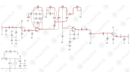
Ok, I've built an audio probe, but I'm not sure how to use it. I've got the jack on the probe going to an amp and I'm running an audio signal trough the circuit from my phone. I hear the music when I probe the jack, the input on the switch pcb, the in on the main pcb, and the lead of R1 (but not the lead going to ground). I would expect to get an audio signal from probing C1, the next component in the audio chain but I don't get anything. I did some hunting and pecking with the probe to see if I could find the signal further down the line and I detected a very faint signal on pin 3 of the IC and the emitter of Q1. oxide schematic.PNG
 
Last edited:
Intermittent problems can be hard to identify. Working and then not working usually signifies damage to the pedal, unsound wiring, or janky soldering. Do you have continuity between the non-grounded side of R1 and C1?
 
I've tried testing again and now I get a clear signal on pin 3 of the IC but nothing on any of the other pins or any of the components in the clipping stack. I do have a 47pF in place of a 51pF since the 47pF measured closer to 51pF than the actual 51pF I had in there before.
 
I've tried testing again and now I get a clear signal on pin 3 of the IC but nothing on any of the other pins or any of the components in the clipping stack. I do have a 47pF in place of a 51pF since the 47pF measured closer to 51pF than the actual 51pF I had in there before.
I'm not sure what's changed but now I get a signal on pin 5 of the IC, but a very faint signal on Pin 7 and all of the components in the stack between those two. I've tried reflowing the solder but no change.

EDIT: Now the signals not coming through pin 5 again. Thanks for your help everyone but I think I have to tap out on this one, its just too inconsistent to nail down the problems.
 
Last edited:
I'm not sure what's changed but now I get a signal on pin 5 of the IC, but a very faint signal on Pin 7 and all of the components in the stack between those two. I've tried reflowing the solder but no change.

EDIT: Now the signals not coming through pin 5 again. Thanks for your help everyone but I think I have to tap out on this one, its just too inconsistent to nail down the problems.
I'm a glutton for punishment so I went at it again. I replaced the IC with a JRC 4580D and then the signal started going all the way through the IC again so it looks like that was one of the problems. I was able to trace the signal to the input base, pin 3, on Q2 where it sounds fine, but the signal is very weak and distorted coming out into the emitter on pin 1 so it looks like that's where the problem is for now. I've tried at least 3 different transistors in that spot and it hasn't made a difference. Another one from the same bag is in Q1 and is working fine. Any ideas?


EDIT: It also seems like there is something going on with the IC. It will work for a little while then stop. Then if I put a new one in the socket, it will start working for a while then stop. If I put the old one in it will work again for a little while again.
 
Last edited:
Back
Top