PAL800 v3: the switches

Elijah-Baley

Active member
Hello, I have a question about the PAL800, the JCM800 Emulator, the PedalPCB version is the M800:
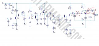
The schematic is a jfet version of a JCM800 preamp: six transistors with five trimpots. That was the old version of the PAL800.

There's a V3 version, now, that includes the same controls, but with a 3-way toggle switch that change the bass and mid response, especially at low gain setting. At max gain setting (from the official web site information) it doesn't make anything.
Another toggle switch for the #34 mod and a footswitch to alternate the stock high input with the low input.

Here's the official page:

And this is a gutshot I found:

4sMzdsO.jpg


You can see there's only three... transistors? Those thing are called Q1, Q2 and Q3 and look strange. But just three? And the trimmer? There's just one for the inner master tone control.

The #34 Mod I know is some parts changed or added in the JCM800 preamp. How in this circuit a SPDT switch can make just one change and reach more or less the same mod?
And does the I/II footsiwtch follow the original JCM800 schematic?

What do you think about all this?
 
Monolithic Dual JFETs? I didn't know them, but I think you could be right. So three transistors, but actually those are six.
The trimpots are missing, but maybe those kind of transistors are more accurate, or if it possible, matched or selected to work ok with a specific resistor value.

The Footswitch I/II for the High Input / Low Input can do it, if it like the original Marshall amp, bypassing, in the Low Input mode, the first stage and going directly into the first 470pF/470k. If I get well the schematic. Maybe keeping the pull down resistor 1M to the ground.

About the two toggle switch is a bit more complicated. We should try count the components to compare it with the stock original version, to get some clues.

Edit: Caps and resistors are definitely more than the stock schematic!
 
Last edited:
Yes, they are tightly matched and stable making the trimmers unnecessary. They aren't cheap but neither are 6 fet/trimmer pairs.
 
They look standard to me in a 6 pin monolithic can. They might have painted them black to obscure part numbers.
 
  • Like
Reactions: fig
I was not familiar with those transistors at all. very interesting. almost surprising there is even a through-hole version available.
 
Probably the schematic is still based on six transistors. At this point I'm really curious about the switches.

amysBUg.jpg


«#34 Toggle Switch: This switch will allow you to achieve the famous MOD #34, a modification that can be made in a 1959SLP or JCM800 amp and that has been the main tone of one of our favorite guitar player "SLASH". When the toggle switch is in the down position you will be in the MOD #34 and in the upper position in the original PAL800 GOLD Overdrive design. For a more accurate result of the MOD #34, please put the Gain Voicing switch in the down position and set up the Gain knob around 12 to 2 O’clock using your favorite Les Paul.»

As I told this mod adds and replaces some parts in different spots of the schematic, so I guess it can't do it in the same way with just a SPDT switch. I think the #34 mod add gain and push mid, maybe it makes the low end a bit tight.
This is the mysterious part. Because it could have to do somehow with the extra components. Else I can't explain why it has a bunch of caps and resistors more than the stock basic version.

«G. VOICING Toggle switch: This three-position switch will allow you to get different tone responds (Voicing) in the gain section of the pedal, the change between positions will be more radical at low gain settings and smoother as you turn up the "Gain" knob. At maximum "Gain" knob position this switch will not affect the gain voicing respond.
The middle position is the most flat respond setting of the three positions, ideal to use at low gain settings (bellow 11 o'clock position of the "Gain" knob), the lower position will give you more middle and bass response and the upper position more brightness and less bass response.
Each position will affect the output volume level of the effect depending of the "Gain" knob position, in this case, you will need to adjust also the "Volume" knob to your taste when you use the "Gain Voicing switch".
»

I thought it changes the bypass cap in the first transistor stage. But a pair of things make me think that I was wrong. So, this switch could add two different caps, or none, between the lug 2 and 3 of the gain pot, instead. This makes more sense.

«INPUT I/II Footswitch: This footswitch recreates the same input circuit section that you could find in some classic Marshall amps like the Plexi, in this case the "Input I" will be 6dB louder than the "Input II". When the led indicator is OFF you will be in the "Input II" section and when is ON in the "Input I". This feature will allow you the get the same behavior as in the real amp at low and high gain settings in terms of attack, dynamics and interaction with your guitar volume control.»

The footswitch probably bypasses the first stage, mainly. We can see at least a pair of resistors and a electrolytic caps close to the footswitch.
 
As I told this mod adds and replaces some parts in different spots of the schematic, so I guess it can't do it in the same way with just a SPDT switch. I think the #34 mod add gain and push mid, maybe it makes the low end a bit tight.
Maybe this switch does not incorporate all of the #34 mod changes. Just the most important.
 
I'm trying to emulate the circuit to find out how.
Meanwhile, I tried to see what happens if I bypass the first stage going directly on the 470k/470pF: there's a big gain/volume loss, more than only 6db.

Here's the schematic.


PAL 800.png
 
I think you can try to add a Q2 or Q3 source bypass cap as a simplified 34mod. I've just tested tube JCM800 preamp in ltspice.
Cathode bypass caps have the most visible effect from entire mod. I started from the input towards the output
First - 68k to 33k. Then 100k anode resistor to 50k. Then 470p to 2.2n. Next added 150k. Then 100n, then 470n.
Below are the frequency response plots for each change.
And effect of the 100n source bypas cap in PAL circuit- Q2, Q3, Q2 + Q3. But you would have to find a way of cutting some lows
 

Attachments

  • 34mod.png
    34mod.png
    267.1 KB · Views: 17
  • pal34.png
    pal34.png
    151.2 KB · Views: 15
Last edited:
;) It's the sort of things I did.
Except this:

[...] Then 100k anode resistor to 50k. [...]

I'm not sure what is this thing you did.
The 34mod I found adds a 220pF in parallel with a 100k in the first stage, the only step I have and you don't. In the jfet version is in parallel with the trimmer.

I don't know why bypassing the first stage I got a big volume loss, I hope that is just a kind of joke of the software. Else, I could cut 6db of gain adding a resistor to the ground after the input one, like a voltage divider. A real pot in front could be a Pre-Gain control for any setting.

We really need to track this PCB, all that caps and resistors make me think there's something more than we can see. It's impossible doing using just that picture.
I'm really curious about it.
 
Oh.. looks like there's more than one #34 mod description. The one I took calls for first tube 50k anode resistor (two paralell 100k), not a paralell 220p cap. To cut some low end you can lower value of the R7 to 220k.. 100k. Experiment.
 
Thank you.
These are all things where I can take advantage in case I'll build this circuit.

Anyway, I really think that the newer version, are basically the same schematic, but with something more. Even simple version of the PAL 800, the one without the second footswitch and the #34mod, has a bunch of extra caps and resistors.

This is a gutshot of the simple one with just the voicing switch on the side, no footswitch, no #34.

PAL 800 gutshot - small.png

The position of the parts is different, and I guess this has about the same parts of the bigger pedal, and this could be helpful to identify some components, even if I know it's almost impossible draw a schematic in this way.

We can read just some caps that maybe we know: the 470nF (output?), the 680nF the bypass cap in the first stage, the 2.2nF, the grey labelled 222, for the Presence pot, and the next one a bit bigger (more than I used to buy), could be the 100nF? The red caps could be the 22nF, the stock schematic has six.
In the left up corner we have a bigger and a slim caps, I can't match them with the schematic. The little ceramic should be the 470pF of the Treble pot. The monolithic yellow caps could be the 470pF in parallel with the 470k resistors, for some reason are better quality type.
I can see two electrolytic caps, and not just one, 100uF, in the power supply. I think that is the one next the diode.
I see a cap with 472 code: 4.7nF? Other three red caps... I can't follow it.
 
I'm trying to emulate the circuit to find out how.
Meanwhile, I tried to see what happens if I bypass the first stage going directly on the 470k/470pF: there's a big gain/volume loss, more than only 6db.

Here's the schematic.


View attachment 10565
I've build an identical pedal using the pcbmania circuit, but I can't understand why in the output section there are some differencies between the circuit posted here and the one I followed, in red the differencies... Anyone has an idea of what can those components influence the sound?
 

Attachments

  • 800differences.jpg
    800differences.jpg
    313 KB · Views: 83
Well, I think it's just a different approach to the jfet version of JCM800. Consider that the original amp schematic doesn't have R19, C13 and C14 (in pcbguitarmania. schematic) nor C13, C14 and Trim4 (in PedalPCB schematic) because in the tube version, I'm not an expert, works difference, I assume.
So that is just a way to filter the treble in excess and set the low end response.

PedalPCB is like the original PAL 800 in every part, so it has a 470nF, I think enough to avoid low end loss, and a trimmer that, with the 10nF, make an inner tone control to cut treble.
While the pcbguitarmania is not a replica of the PAL800, but simply a JCM800 jfet version. I think that the R16 2.2k tames a little bit of gain and treble, then the 6.8k and the 10nF make fixed llow-pass filter (none inner tone control), and the 1uF cap avoid the loss of the low end.
 
I guess it will make almost no difference.
I'd say if you can hear too much treble you can increase the 6.8k resistor.
 
Back
Top