Paragon Build Assistance

JamesWheeler

New member
Hi all,

After spending what seemed like an eternity to collect all of the components for the Paragon build finished up assembly this morning.

Frustratingly, when I went to plug in it seems I've created a dead box. No LED's when foot-switches are triggered. No sound either. Sound of silence. hello darkness my old friend.

I have rechecked and flowed a lot of the solder joints. Specifically around the power and in tout jacks. To no avail.

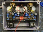
I have attached some photos, can anyone spot my error?

best

Wheels
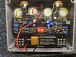
61445717007__EB4A4C57-A9DE-440C-A7DC-F106B6EE7823.jpg
 
Neither of these are likely to be causing your issue, but usually I think the two ground wires going to your Input jack are swapped around the other way. (Battery to Ring, PCB ground to Sleeve)

Also, if the Yellow wire coming from your Output jack is going to the pad on the right, the black and yellow wires will need to be reversed. (hard to tell from the pic)

Now as for your issue... Do you get the same thing when running on battery and DC power supply?

Do you have a DMM to make some measurements?

I was just trying to accurately follow the Schematic on the website.

I flipped over the two ground wires on the input jack

I also just changed the two wires on the output.

the problem still persists on both 9v power and battery.

thanks for the assist
 
Post a fresh pic with the changes you made, your input looks like it's connected with a ground in that picture, probably need to see the other side of that board as well
 
no sound even when you bypass the effect?

time to start learning how to use your DMM. find out if you have 9V at the PCB from your power jack when your power is plugged into it with the battery removed. then unplug the jack, connect your battery and see if you are getting something close to 9v at the + and - on your pcb.

then switch your probes on those two points to see the difference between a positive voltage and a negative voltage to make sure you have those wires connected correctly.

IF you have voltage coming in to the board like it is supposed to, you can use your schematic and see if you are getting power at the points where you should be.

over to the university of YouTube it is then!
 
Are you sure those yellow in/out wires are going to the correct lug on those jacks? I’m not familiar with those jacks cuz I don't use them, but they may need to go to the other lug. If you have a 1/4” pedal coupler you can plug it into the jack and do a continuity test to verify the lugs.
Also that ground wire from jack that goes into pcb looks like it needs more solder...unless you have it soldered on other side?
 
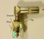
You can use a guitar cable too. Plug it into one of the jacks and do continuity test on other end of cable. Base of plug (to jack lug) will be ground, and tip (to jack lug) will be signal.
 
Are you sure those yellow in/out wires are going to the correct lug on those jacks? I’m not familiar with those jacks cuz I don't use them, but they may need to go to the other lug. If you have a 1/4” pedal coupler you can plug it into the jack and do a continuity test to verify the lugs.
Also that ground wire from jack that goes into pcb looks like it needs more solder...unless you have it soldered on other side?

I'll double check the in out wires are going to the correct lugs. I don't have a coupler unfortunately.

the DC jack wires are soldered on the underside, but I can add a little more solder on the top side.
 
I'll double check the in out wires are going to the correct lugs. I don't have a coupler unfortunately.

the DC jack wires are soldered on the underside, but I can add a little more solder on the top side.
It could be hooked up correct, but I always use a coupler/cable, and my meter to make sure, especially if its a jack I’m not familiar with. Plus it’ll give you an opportunity to get familiar with your meter which is essential.
 
It could just be dirty, but looks like there may be damage to some of your traces.

That style of DC jack uses a mechanical switch to change power supplies and may be damaged or faulty. This is always going to be a possibility with moving parts. You can use a DMM to verify you're actually getting 9v to the jack. Start from there and work your way down through the pedal. I've had a repair that was as easy as replacing the connection from the DC jack to the board.

Some of your solder joints look very cold, particularly the I/O jacks, DC jack and left 3PDT. If you have some, I'd recommend using a little bit of flux and reflowing them. This could be because your iron isn't hot enough or if you're using lead-free solder.

It's also best practice to use a socket for IC's, it can help with troubleshooting and suspected faulty parts. Not that I think that's the problem here, but it sucks when you've spent ages on a build and have to either attempt to remove an IC or destroy it and risk burning the board.
 
Also, if you're testing with the battery rather than a 9v wall wart, plug a lead into the input. Without this your battery power will not ground, and without a closed circuit you won't be getting any power.
 
I’m not familiar with the 4560 IC, I used the 4580’s on my 2 builds that are called out for in the build docs. I’m assuming they are compatible?
 
A most folks have said double check you've got your IN and OUT sockets wired correctly

If you don't get bypass or effects signal then your jack wiring may not be correct even without power or if you accidentally put your in cable into your out socket and visa versa you'd should still get bypass signal

Stick a jack into the socket then just follow the connections round to the solder lugs for tip, ring and sleeve / ground, like this

jack.jpg
 
Back
Top