SOLVED Parentheses octave troubleshooting

joeyd

Active member
I've read through a litany of Parentheses troubleshooting threads and I haven't quite been able to sort out the issue I'm having - as I turn my octave pot clockwise it cuts my volume. As far as I can tell I've got my resistors in the correct locations. Here's what my transistors are reading (from what I've read many of these values aren't correct but I'm not sure how to use them to troubleshoot my issue):

Q1:
drain: 8.85v
source: 0.87v
gate: 0v

Q2:
emitter: 0.25v
base: 0.8v
collector: 6.3v

Q3:
emitter: 8.85v
base: 0v
collector: 0v

Q4:
emitter: 3.79v
base: 0v
collector: 8.85v

Q1:
drain: 8.85v
source: 0.81v
gate: 0v

I'm not having any issues with the boost or distortion side - they sound great (although op-amp and si/led clipping options sound identical). It's also worth mentioning that I sourced my transistors from Stompboxparts and Amplified Parts (not Ebay, Amazon, AliExpress, etc.).

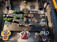
parentheses internals.jpg
 
As far as I can tell. I originally had 1n34a diodes but swapped in Schottky diodes to see if that was the issue. It wasn't.

I'm also pretty sure the orientation is correct. After reading so many threads on troubleshooting I would feel foolish if that were the problem. I referenced the silk-screening on the PCB.
 
There is quite a bit of solder on the Schottky legs and something funky happening on the right-most pads, maybe due to the substitution. Asking out of ignorance: could there potentially be a solder bridge that would suck the signal the more you increased the signal from that sub-circuit?
 
As far as I can tell. I originally had 1n34a diodes but swapped in Schottky diodes to see if that was the issue. It wasn't.

I'm also pretty sure the orientation is correct. After reading so many threads on troubleshooting I would feel foolish if that were the problem. I referenced the silk-screening on the PCB.
Germanium diodes are not always banded the way we expect them to be. Do you have a datasheet or maybe info from the seller about which band = cathode/anode? Might be worth checking and confirming while you’re in troubleshooting mode.
 
Germanium diodes are not always banded the way we expect them to be. Do you have a datasheet or maybe info from the seller about which band = cathode/anode? Might be worth checking and confirming while you’re in troubleshooting mode.
Can also do this in continuity mode with a multimeter, both probes on either end. Red probe will either read 0, and that will be your cathode (-) or some value, and that will be your anode (+)
 
Germanium diodes are not always banded the way we expect them to be. Do you have a datasheet or maybe info from the seller about which band = cathode/anode? Might be worth checking and confirming while you’re in troubleshooting mode.
The Ge clipping option on the rotary version of this circuit orientation doesn't matter, as long as they are opposing polarity it can go either direction. I don't think that the Ge's would affect the Octave issue and focus elsewhere.

Screen Shot 2022-11-17 at 8.10.43 AM.png
 
I built it and it works a treat. The advice on trying to find a matched set of Ge around 300fv 3.00fv is a good one. Makes for a more distinct octave effect. I didn't have volume issues, so I'm suspecting something in the build, like a fault or short in the circuit that would become more evident the more you blend in the octave signal.
 
Last edited:
Ive had a very tough time finding any GE diodes that will measure over .28
Most of my Russian D-series measure over .300 on my CCT, which tests at 10ma. Which translates a little lower on the curve if the spec is "matched set of Ge diodes ~Vf .300mv @5ma". I would need to target high 300's or 400's.

I can scare up a set for you from my stash and pop them in the mail to you.
 
hahaha... that's my historian brain inattention to electronics detail. I meant .300 -- just have to scooch that decimal about, but at least the digits are right!
Ive had a very tough time finding any GE diodes that will measure over .28
stompboxparts has russian Ge diodes as well as the 1N914 diodes--and I actually have a tough time finding any that measure under .300. Most are .400-.600-ish--they are not particularly consistent. Had two 1N914 @ .450-ish for the octave in the Parens but I think the octave effect works better with the Russian ones I swapped in that are .340 or so. (It may also be that I didn't particularly match the set of 1N914s --like I said, lack of electronics mindset here).
 
Last edited:
Most of my Russian D-series measure over .300 on my CCT, which tests at 10ma. Which translates a little lower on the curve if the spec is "matched set of Ge diodes ~Vf .300mv @5ma". I would need to target high 300's or 400's.

I can scare up a set for you from my stash and pop them in the mail to you.
It's all good.. I use what I have and they always sound pretty good!... I probably have 8 different germanium types.. Thanks for looking out!
 
Germanium diodes are not always banded the way we expect them to be. Do you have a datasheet or maybe info from the seller about which band = cathode/anode? Might be worth checking and confirming while you’re in troubleshooting mode.
I'm thinking it might be transistor/s, not the diodes. The readings that I put up look very wrong. My son likes to play with my multimeter, so it's possible that my weird readings may be related to that, but there are three transistors passing ~9v and it's my understanding this is very wrong. I triple checked that I installed 47k resistors not 4.7k or something else - seemed like something at least a couple other builders ran into. All my values looked right. It's possible there's a bad resistor.

I don't think there are any solder bridges. I think the angle of my picture isn't doing me any favors. I'll clean that joint up anyways.

I'm just getting back around to troubleshooting this thing. Had a kid a week after posting and I've been preoccupied.
 
A kid a week? How many wives / girlfriends do you have? ;)

Going back to your first post...
Q1 voltages are good
Q2 voltages are good
Q3 voltages are not good. Either there is something wrong with how you're making the voltage measurements, or you have a bad solder joint or broken trace. Q3-B connects to Q2-C, so they should always read the same voltage.
Q4 voltages tell me that you're not making contact with the base lead when you make the measurement. Q4-E & Q4-C look correct.

The symptom "...as I turn my octave pot clockwise it cuts my volume." says that Q4 is working but no signal is getting to Q4. No signal is getting to Q4 because Q3 has a problem. Do some (more) visual inspection and figure out what is wrong with Q3. Wrong part? Damaged part? Broken trace? Bad solder joint? Re-run the Q3 voltage measurements.

C4 & C5 are completely obscuring Q2-Q4 in your photo, so we can't help you with inspection of those devices. Take the board out, inspect the solder side and show us a pic of the solder side. Make sure everything around Q2-Q4 & R5-R15 is visible.
 
I built the mini version of this and have the exact same issue, when I turn on the octave part the knob basically becomes a volume knob.. di you manage to find the issue?
 
I built the mini version of this and have the exact same issue, when I turn on the octave part the knob basically becomes a volume knob.. di you manage to find the issue?
I haven't, unfortunately. I have a growing pile of builds that need to debugged but the amount of effort it takes to fix is so much greater than just building something new (I ended up sticking a green ringer in a DRV clone and called it close enough).

I was going to start with Chuck's suggestions. I put an audio probe together that I've been using to fix an Arachnid that won't pass analog signal. I'll probably start with that to narrow down the problem. I don't think I lifted any traces (hopefully) while I was soldering but I'll reflow the joints and retest the transistors.
 
I figured this one out and thought I'd update just in case someone finds this thread in a search. Turns out you need to use the right transistor for a circuit to work. I foolishly stuck a 2n5457 where the 2n5087 should have gone. I didn't have a 2n5087 around and subbed a 2n3906. Now everything sounds great (and only took 11 months to successfully troubleshoot).
 
I figured this one out and thought I'd update just in case someone finds this thread in a search. Turns out you need to use the right transistor for a circuit to work. I foolishly stuck a 2n5457 where the 2n5087 should have gone. I didn't have a 2n5087 around and subbed a 2n3906. Now everything sounds great (and only took 11 months to successfully troubleshoot).
Welcome to the club. For future reference, they expect you to put in all the ICs, too. I may or may not still do that.
 
Welcome to the club. For future reference, they expect you to put in all the ICs, too. I may or may not still do that.
I should have clued when I built a war scythe immediately after and it didn't need a 5457 for the green ringer part of the circuit. Those transistors were tough to source too (at least they were a year ago when I was still figuring out where to buy components) - I needed them for a mosfeta build. Ugh.

I've definitely boxed everything up a few times forgetting the ICs. Putting things together and getting (good) sounds out makes the frustrating builds worth it though.
 
Back
Top