SOLVED Parentheses V1 early make

Allthumbs

Active member
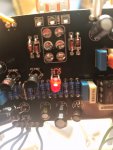
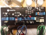
Finally getting to this build and have a couple of issues here. I've read the other posts on this one and I'm still confused. While all sections seem to work, the octave is not really audible and there's a lot of noise in the signal.

1st question that may solve it is...does the misprinted clipping LED mean that the Anode goes to the square pad, or is it reversed and still goes to the round pad?


20200406_092549.jpg 20200406_092753.jpg
 
Check the V2 build docs, it explains the diode configuration from V1 to V2. Did you measure and match your diodes Vf? Your octave switch wire pad soldering looks not so great, try not to let loose wire stick out. Really butt it up to the pad.
 
Check the V2 build docs, it explains the diode configuration from V1 to V2. Did you measure and match your diodes Vf? Your octave switch wire pad soldering looks not so great, try not to let loose wire stick out. Really butt it up to the pad.
yeah, I wired them backwards and tried to reinsert them into the holes when I flipped them around. not so good. thanks
 
Also, those build notes talk about the D2, D3 on V1. I'm talking about D6 3mm Red LED The build docs show the Anode being the round pad but the actual board has it as marked Anode a square pad, which is reversed. Wondering if the pads are wrong or the symbol on the board is wrong. Currently I have the Anode to the round pad even though it's labels with a K
 
Last edited:
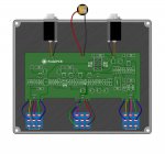
Not knowing much about switching except to replicate what I see, is the lack of the diagonal bridge on the right switch correct? It's on both Boost and Rat switches in V2, V1 shows only Rat getting this diagonal switch bridge..... Parentheses_page6_image5.jpg
 
Last edited:
everything works great. this is the most complex pedal for me yet, very happy to have it. wrecked an LED pad though. not sure how I'll fix that.

pedal sounds like a beast

the boards are double sided so there's a pad on each side. You might be able to poke the leg through and solder it to the other side to make the connection. Or, if not, find out to which component the leg is connected and solder it to there. I've had to solder cap legs to resistor legs before through screwing up pads and when I do I run a croc clip from the receiving parts leg to the chassis to dissipate heat (if there's room).
 
the boards are double sided so there's a pad on each side. You might be able to poke the leg through and solder it to the other side to make the connection. Or, if not, find out to which component the leg is connected and solder it to there. I've had to solder cap legs to resistor legs before through screwing up pads and when I do I run a croc clip from the receiving parts leg to the chassis to dissipate heat (if there's room).

perfect, thanks.
 
Back
Top