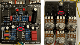
Please tell me I didn't install these in the wrong direction

jojoChambana

New member
Hello all, this is my first attempt to build an effects pedal. I am second-guessing my installation of the transistors in the photo below. This is a Delegate Boneyard compressor. I am still waiting on a couple of parts so I haven't had a chance to test it out yet. Something tells me I'm going to have to desolder the pots to get to these transistors. Any help would be appreciated. Thanks! IMG_0503.jpg
 
sorry to say, they are in backwards. You might want to try using sockets for transistors, ICs (I see those there (y)), and other components like clipping diodes.
 
Damn son, off to a rough start? It happens, doesn’t let that discourage you. We learn from our mistakes... and I bet you won’t do that again.
I went into this headfirst with blind confidence figuring I'd learn as I go. I bought two and built them at the same time. Double the hard lesson. Yup, I learn stuff the hard way,
 
  • Like
Reactions: fig
@fig The D4 was soldered in wrong for sure. I fixed that. The white strip indicating polarity on the D101 was printed only on one side! Luckily I can see it is installed correctly. Going through the others to make sure they are correct. Thanks again for the heads up!
 
  • Like
Reactions: fig
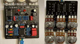
So I able to turn the transistors around along with the D4 diode. I assembled the pedal and gave it a whirl. I got no sound but the C3 100n Wima capacitor got so hot that I could smell it. I managed to get it out but I'm still working on getting one of the pins out. Would anyone dare take a guess what I've done wrong? Please be kind, this was my first attempt at soldering a pedal and I assembled two of these of them at the same time. I don't know why I thought it was a good idea.

tested.png

untested.png
 
Did you replace the burnt caps? I'm a little unclear on what you're asking with those (C8/C6).

For C3 - do you still have a piece of the lead stuck in there? It looks like you may have taken the solder point off with all of the heat, which could mean that even if you get the remainder of the lead out that you may not be able to solder it, and if it does solder, it may not make a connection with the trace in the board.

If that is what happened (I'm not sure that it is as I can't see the hole all that well) you can likely still use the board but may have to jumper it (whatever you do, don't bin it! once the problem is found someone here can most likely help you find a fix). C3 goes to R3 and to ground, but that's as confident as I can be looking at a schematic right now, you'll need someone with more experience than me to tell you which pad to jump to if that is what's needed.

When you're de-soldering, if you don't get it the first 2 or so times, let it cool off for a while before getting back to it. These things heat up incredibly quickly and they take a while to dissipate that heat. Take a shot at de-soldering, if it doesn't work, do something else for a little bit and give it another shot. Patience is your friend here.

You'll get a feel for what works for you and the more you do it the better you will get. Someone will drop in who is (much) more knowledgeable than I am and be able to point you in the right direction. Keep it up, dude.

Edit to add: It also looks like IC1 in the first photo is in upside down. If you've powered it up you will probably have to replace it.
 
Maybe it got burned out while IC1 was socketed backwards. I see you discovered that and turned it around for the 2nd pic. Does the OPA2134 still work?

You might want to use film caps for C1 and C4. Since tantalum caps are polarized, and if you're playing fast-and-loose with polarity, there's probably a 50/50 chance one of them is reversed. Good luck!
 
What Peccary said about saving the board... keep it, even if you've managed to lift a trace.

My first ever project had a clean-blend daughter board that I overheated a pad so badly it fell out of the PCB and the trace that it had been attached to was mangled beyond belief, or repair for that matter.

It was almost done when I crispifried it, I thought I'd have to start over with a new board — my friend/mentor calmed me down and showed me I could just attach the wire further upstream. I followed the trace to the next component and soldered my wire on to that next component's exposed lead. Wasn't pretty, but it worked.

Take your time, that's what did me in, I was rushing to get that first project finished in time to enter it in a "pedal-building" competition. Needless to say I didn't get 'er done in time to collect Best Noob prize.


Stay the course, you'll get there. Eventually.
 
Did you replace the burnt caps? I'm a little unclear on what you're asking with those (C8/C6).

For C3 - do you still have a piece of the lead stuck in there? It looks like you may have taken the solder point off with all of the heat, which could mean that even if you get the remainder of the lead out that you may not be able to solder it, and if it does solder, it may not make a connection with the trace in the board.

If that is what happened (I'm not sure that it is as I can't see the hole all that well) you can likely still use the board but may have to jumper it (whatever you do, don't bin it! once the problem is found someone here can most likely help you find a fix). C3 goes to R3 and to ground, but that's as confident as I can be looking at a schematic right now, you'll need someone with more experience than me to tell you which pad to jump to if that is what's needed.

When you're de-soldering, if you don't get it the first 2 or so times, let it cool off for a while before getting back to it. These things heat up incredibly quickly and they take a while to dissipate that heat. Take a shot at de-soldering, if it doesn't work, do something else for a little bit and give it another shot. Patience is your friend here.

You'll get a feel for what works for you and the more you do it the better you will get. Someone will drop in who is (much) more knowledgeable than I am and be able to point you in the right direction. Keep it up, dude.

Edit to add: It also looks like IC1 in the first photo is in upside down. If you've powered it up you will probably have to replace it.
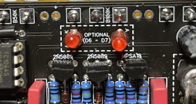
The great news is that the second set of photos is working both on the testing board and installed in a Tayda box. So I have one working and complete compressor now! The board depicted in the first set of photos does this hilarious thing when I attach it to the testing board and flip the bypass switch. The LED briefly lights up then dims to nothing while my amp makes the sound of a droid powering down. I need to redo the photoresistor set up so it is standing upright like it is in the first set of photos. This positioning makes it easier to deal with from my amateur perspective. Stay tuned, I will get this!
 
Maybe it got burned out while IC1 was socketed backwards. I see you discovered that and turned it around for the 2nd pic. Does the OPA2134 still work?

You might want to use film caps for C1 and C4. Since tantalum caps are polarized, and if you're playing fast-and-loose with polarity, there's probably a 50/50 chance one of them is reversed. Good luck!
These are all good points. Like I told Peccary, I got the one in the second set of photos working. I was able to get the broken 100n cap leg out on the other and soldered in a replacement. I think I ordered enough replacement parts to replace all the burnt caps and just ordered other parts from Mouser for a Kliche pedal. I might have some tantalum caps between these orders.
"Pil Sung!"
 
Back
Top