SOLVED Polyhog issues: volume and bass pot not working correctly

quazimoto

New member
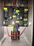
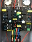
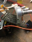
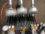
Greetings! Hope everyone is doing well through all the craziness this year. The issue I am having with the Polyhog is the volume output is very low all together and the volume pot works as expected (still not a lot of volume output) until maybe the last 1/3 towards max and it then starts to go the other way getting quieter. The bass knob does the same. It works until the last 1/3 then it seems to stop adding bass and starts to remove signal volume. The other pots seem to work as they should. Initially I thought a bad solder joint or I had a electrolytic cap backwards but everything seems to match up and I used a jeweler's lope to go over the board looking for shorts. Staring at the schematic I tried swapping out the op amps (IC1 and 3) but nothing changed. Any help on where to start testing or what the problem could be would be appreciated. Thank you!
 

Attachments

  • polyhog 2.JPG
    polyhog 2.JPG
    2.1 MB · Views: 16
  • polyhog1.JPG
    polyhog1.JPG
    1.9 MB · Views: 15
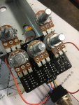
Are your pots insulated? IE: the bare metal covered up so they aren’t touching the solder side of your board.

Also your values look fine from here but I can’t be sure of the 150r as it’s doubled up.
 
Last edited:
I did use pot covers for the bottom three. I did not have a 150ohm so I made a 147ohm. I will take it apart just to verify nothing punctured the pot covers.
 
Nothing grounding on the back of the pots. I tested the IC voltages and these are the results:
IC 1 JRC4558
1. 1.48
2. 1.5
3. 1.4
4. 0
5. 4.5
6. 0.5
7. 1.46
8. 9.1

IC 2 TL072
1. 5.9
2. 5.9
3. 5.9
4. 0
5. 1.46
6. 1.46
7. 1.45
8. 9.1

IC 3 JRC4558
1. 1.48
2. 1.49
3. 1.45
4. 0
5. 1.45
6. 1.49
7. 1.49
8. 9.1

IC4 CD4049
1. 9.1
2. 9.0
3. 0
4. 3.6
5. 3
6. 3
7. 3
8. 0
9. 3.07
10. 3.07
11. 3.07
12. 3.07
13. 0
14. 0
15. 9.1
16. 0

IC 5 JRC4558
1. 1.46
2. 1.53
3. 1.45
4. 0
5. 1.48
6. 1.5
7. 1.5
8. 9.1
 
Last edited:
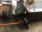
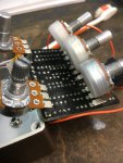
Here are some pics of the solder side:
 

Attachments

  • 52B470DD-ABBD-4897-809C-F5D863676465.jpeg
    52B470DD-ABBD-4897-809C-F5D863676465.jpeg
    1.6 MB · Views: 3
  • AFA7A12C-ABA3-405A-AD23-5BE1632DCEE7.jpeg
    AFA7A12C-ABA3-405A-AD23-5BE1632DCEE7.jpeg
    2 MB · Views: 3
  • 738BB686-F64F-4E1C-B11D-CCBEC819B8EA.jpeg
    738BB686-F64F-4E1C-B11D-CCBEC819B8EA.jpeg
    1.4 MB · Views: 3
  • CF83CAA5-3497-48C2-84CF-ECB61A05892D.jpeg
    CF83CAA5-3497-48C2-84CF-ECB61A05892D.jpeg
    1.9 MB · Views: 3
  • 18BAC1EC-9DA8-4CA2-95A8-C9699D9C5A8E.jpeg
    18BAC1EC-9DA8-4CA2-95A8-C9699D9C5A8E.jpeg
    1.4 MB · Views: 3
Here is a short video trying to show the problem. I notice now the volume pot acts more like an “on/off”. Doesn’t seem to have any taper/effect unless it’s all the way ccw then there is no sound. The bass is under the volume. It works until about 2/3 the way clock wise then volume starts to disappear like it’s slowly grounding out.
 
IC 1.2 is not giving you the correct Vref. Pin 5 is 4.5 volts which should be correct, pins 6 and 7 should be close to 4.5 also. This is being used as a voltage buffer, and its not buffering to 4.5 volts. If you look at IC 2, IC3 and IC5 you'll see that pins 1, 2, and 3 are close and pins 5, 6, and 7 are close on their respective op amp. These are working but the Vref is low at about 1.5 due to IC1.2. You can try to reflow IC1 pins 5, 6, and 7. It may work, if it does not then remove IC1, check that pins 6 and 7 are shorted together. Then check pin 7 resistance to GND, it should be high with IC1 removed. If the resistance is good, try replacing IC1
 
Last edited:
Gentlemen, thank you to the both of you for your help! Got it working correctly. Had no continuity between pin 6 & 7 on IC 1 even after flowing some more solder over the pins. Jumped the two on the bottom of the board now pins 5,6 & 7 all read 4.5v.
 
Back
Top