At the risk of outing myself as a bigger dummy than my previous post...
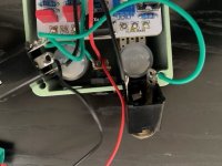
So, let's assume you are working on your first pedal, the Aion Proxima, and, in the midst of a massive brain fart, you wire the DC jack backwards...oops. Possibly luckily, you are just testing the LED and the spidey senses start tingling pretty quickly. Hmm, weird, the battery is pretty hot. Ohhhhhh....
 Nothing else is visually torched.
Redo the jack. LED turns on, but seems dimmer than it should. Engaged, the only thing that seems to work is the clean volume.
Probing around with the DMM exposes continuity on C13 and R17 and R18 both reading less than 10K (one is about 0K and the other about 5K).

Can I assume that D1, C14, and C12 are likely toasted as well?
The other obvious anomaly is R3 which is also reading less than 10K (~5K).

Voltages on Q1 are:
D = 9V
S = 1.2V
G = 0V
Full schematic here: https://aionfx.com/app/files/docs/proxima_documentation.pdf (P6)
Basically, I'm trying to understand and figure out if I should just replace the obviously damaged parts, the obviously+likely damaged parts, or start over with a new PCB (facetious....worst case, this is probably a good chance to learn more troubleshooting skills). All values double-checked visually. First 10 or 11 resistors checked with DMM.
Appreciate any/all thoughts.
So, let's assume you are working on your first pedal, the Aion Proxima, and, in the midst of a massive brain fart, you wire the DC jack backwards...oops. Possibly luckily, you are just testing the LED and the spidey senses start tingling pretty quickly. Hmm, weird, the battery is pretty hot. Ohhhhhh....
Nothing else is visually torched.Redo the jack. LED turns on, but seems dimmer than it should. Engaged, the only thing that seems to work is the clean volume.
Probing around with the DMM exposes continuity on C13 and R17 and R18 both reading less than 10K (one is about 0K and the other about 5K).
Can I assume that D1, C14, and C12 are likely toasted as well?
The other obvious anomaly is R3 which is also reading less than 10K (~5K).
Voltages on Q1 are:
D = 9V
S = 1.2V
G = 0V
Full schematic here: https://aionfx.com/app/files/docs/proxima_documentation.pdf (P6)
Basically, I'm trying to understand and figure out if I should just replace the obviously damaged parts, the obviously+likely damaged parts, or start over with a new PCB (facetious....worst case, this is probably a good chance to learn more troubleshooting skills). All values double-checked visually. First 10 or 11 resistors checked with DMM.
Appreciate any/all thoughts.
 . My voltage is not dividing correctly (Vb not 4.54V), so I'll go back to R17 and R18 to see if I can get them straightened out. Pin 1 and 4 on both ICs read correctly (9.08V and 0V). Pin 2 and 3 on IC1A operate correctly (pin 3 V 1/2 of pin 2). All the other voltages are incorrect.