Problem PCB Pauper

coccoslash

New member
Hi everyone.
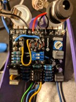
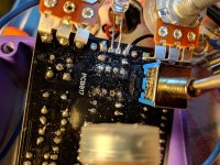
I have a problem on the Pauper. I think I burned the pads where the diodes are soldered (I did various tests changing from Ba283s to 4148s..and I did the damage). Practically the on/off/on selector no longer works. Acting on the switch, the pedal always remains only in the OD position (I think ... or maybe DIST).
Is there a way to bypass the PCB and attach the diodes directly to the switch? Or other solutions?

Thanks so much
 
here they are.
I ask you for information. How many degrees do you set the soldering iron for PCBs? (Celsius)?
Thanks
 

Attachments

  • IMG_20200605_095109.jpg
    IMG_20200605_095109.jpg
    974 KB · Views: 51
  • IMG_20200605_095125.jpg
    IMG_20200605_095125.jpg
    986.4 KB · Views: 50
Im no expert, but judging by your pics, that pcb looks toasted. If it were me I’d salvage what I could off this, get me another pcb, and start over, that’s just me though....chalk it up to a learning experience.
I have one of those cheapie irons and I run mine on lowest setting, which is around 400 degrees F, and I turn it up when doing jacks and switches, also a little flux. Check out the “Basic workflow tips“ thread in general questions section. I’d also socket your diodes next time if you intend on experimenting....good luck and I hope you get it going.
 
Last edited:
I always run mine at 390 to 400 degrees celcius for pcb work

It does also depend on which type of solder you use I personally use 60/40 leaded and never lead free, I just don't get on with it! but a lot of people seem to like it, with lead free I think you'd have to increase your temperature a wee bit

As far as I can see your switch looks ok, as in solder joints and the diodes look to be connected as below, so it'd just be a case of hard wiring your diodes as per the schematic the pads marked with the green dots are the ones that look damaged 2 on the top right and the 4 bottom pads so I think it would just be a case of connecting your diodes via small jumpers as shown

So basically put your diodes through the holes and solder small jumpers (red) where the damaged pads are (green) I'd do it on the solder side of the board and obviously watch to don't apply too much heat to your diodes you only want your iron on them for around 4 seconds or use a small croc clip as a heatsink

ppdiodes.jpg
 
Last edited:
I always run mine at 390 to 400 degrees celcius for pcb work

It does also depend on which type of solder you use I personally use 60/40 leaded and never lead free, I just don't get on with it! but a lot of people seem to like it, with lead free I think you'd have to increase your temperature a wee bit

As far as I can see your switch looks ok and the diodes look to be connected as below, so it'd just be a case of hard wiring your diodes as per the schematic the pads marked with the green dots are the ones that look damaged 2 on the top right and the 4 bottom pads so I think it would just be a case of connecting your diodes via small jumpers as shown

So basically put your diodes through the holes and solder small jumpers (red) where the damaged pads are (green) I'd do it on the solder side of the board and obviously watch to don't apply too much heat to your diodes you only want your iron on them for around 4 seconds or use a small croc clip as a heatsink

Thanks a lot! Ok for the degrees: I use approximately 380C° (with 60/40 leaded).
I'll try to jumper the diodes following your scheme.
I'll let you know. :):);)
 
It should work....but it was late!

As you probably know you're simply bypassing the traces and connecting the components directly

I'd perhaps test your diodes first with your meter make sure they're ok
 
It should work....but it was late!

As you probably know you're simply bypassing the traces and connecting the components directly

I'd perhaps test your diodes first with your meter make sure they're ok
Ok I made these mod, following your scheme (see attached photo).
Now I have UP position OK (should be OD or DIST mode?)..anyhow there's clipping.
MIDDLE position OK (Boost mode, it removes the diodes)
DOWN position: I've another Boost Mode :)..so there's no clipping in down position.
What can I do?

thanks :)
PS
Diodes tested with meter. They are OK
 

Attachments

  • IMG_20200608_232706.jpg
    IMG_20200608_232706.jpg
    336.7 KB · Views: 10
  • IMG_20200608_232714.jpg
    IMG_20200608_232714.jpg
    274.4 KB · Views: 9
ppr.jpg

Perhaps those 2 pads aren't ok, try putting a link there, some of your solder joints are ball like and could be dry inside I'd reflow those
 
Check your switch has continuity in the down position, switched down the middle and top lugs should connect and beep

You've still got a few blobs of solder which could be dry inside I'd try to remove some but carefully I notice your dip switch and a coupla caps are melted a wee bit
 
Check your switch has continuity in the down position, switched down the middle and top lugs should connect and beep

You've still got a few blobs of solder which could be dry inside I'd try to remove some but carefully I notice your dip switch and a coupla caps are melted a wee bit
Yeah 2/3 is not so bad ahaha :LOL:
I check continuity: ok, switched down middle and top lugs are connected.
I also check the continuity of the wires and the diodes (following your scheme) and seem ok.
I'll try to remove the blobs of solder..
 
When it's in the down position does the dip switch, any of the pots or maxing your guitar volume affect it i.e do you get more dirt

As far as I can work out Down would be overdrive mode
 
Here's how the DPDT connects, confirmed by the main man, and after a lot of head scratching and looking at schems

You can continuity check your switch connections to make sure they're connected like this, any VREF point will do to check that lug, junction of R12 and 13, top of R2 etc

pauperdpdt.jpg
 
Here's how the DPDT connects, confirmed by the main man, and after a lot of head scratching and looking at schems

You can continuity check your switch connections to make sure they're connected like this, any VREF point will do to check that lug, junction of R12 and 13, top of R2 etc

View attachment 4866
This is very helpful.
Unfortunately, these two days, I've the painters at home and my laboratory is dismantled ?
Sorry but my English is not so good ( I'm Italian..)..
So, with the toggle up, I'd have the od and with the toggle down the distortion?
As soon as I can I'll test with multimeter the points.
Thanks a lot mate! ??
 
I think so! I don't have the pcb and connecting virtual switches with a schem isn't my best skill!

Distortion you'd flip the switch down connecting the middle and top lugs like a proco rat hard clipping set up .

Middle I think takes the diodes out of circuit for clean boost and flipping the switch up connects the middle and bottom lugs for a softer OD clipping arrangement in the op amp feedback loop more like a tubescreamer

The way the switch connects can confuse, flip it up you'd expect the common middle and upper lugs to connect but no!

Anyway you can have a look here for a bit of info on the rat and ts clipping amps

https://www.electrosmash.com/tube-screamer-analysis

https://www.electrosmash.com/proco-rat
 
When it's in the down position does the dip switch, any of the pots or maxing your guitar volume affect it i.e do you get more dirt

As far as I can work out Down would be overdrive mode

Here I am :)
The down position acts like the center posotion (boost): any pots affect the sound (also the dip switches).
Is like having (1x) OD mode and (2x) Boost mode:rolleyes:
I also check the continuity, as you described, and it seems all ok:(
 
So your switch continuity is good middle common lugs connect to top lugs and flipped the other way middle connects to bottom

Each lug connects to the components detailed e.g. top left to VREF, middle left to D3 cathode and D1 anode and so on

It sounds like D3 and 1 are not conducting

Check that your switch poles don't have continuity specifically the 2 top ones

When you checked your diodes what forward voltage reading did you get
 
So your switch continuity is good middle common lugs connect to top lugs and flipped the other way middle connects to bottom
Yes
Each lug connects to the components detailed e.g. top left to VREF, middle left to D3 cathode and D1 anode and so on
Done..Ok
It sounds like D3 and 1 are not conducting
Check that your switch poles don't have continuity specifically the 2 top ones
Done, Ok
When you checked your diodes what forward voltage reading did you get
D1= 114mv
D2= 125mv
D3= 147mv
D4= 109mv
 
Back
Top Bottom