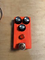
Resinite Overdrive w/ Enclosure Drilling Overview

falco_femoralis

Active member
Hi all, in my other build threads I pick up after the holes have been drilled and focus more on installing the PCB into the enclosure and wiring it up. I wanted to detail my process for drilling each enclosure this time. It is pretty tedious but there is a flow I get into and it's not that bad.. if I don't stop to take pics.

Starting with the bare enclosure I try to see if there are any irregularities I want to stand out or imperfections to cover up. This one has a nice yellow detail near the top which would be covered up by the knobs so I flipped it upside down from this perspective
IMG_5632.jpg

Then I place the components on top of the pedal and get an idea of what knobs to use. I recently picked up some of these synth knobs, which I like because they are kind of like Boss knobs but more elegant. These are the skirted style
K2g8nHf.jpeg


And these are the non-skirted
CULrrhV.jpeg

I went with the skirted ones

then I grab all the components and bring them over to the drill work bench
2dfMtWP.jpeg


I cover it with painter's tape and make note of which end is the top. I make sure to mask off the top and bottom edges as well as at least half of each side as well, and I fold the ends of the tape over to the inside of the enclosure
f02T0Fl.jpeg


Here are some notes I made to remember the center lines of a few enclosure sizes
EIQm8ev.jpeg


Using my combination square as a depth gauge I mark the center
T8y1Eq4.jpeg


Then double check it from the other side. This one I got on the first try
cwzUOBm.jpeg


Then I do it again so I can have two points of reference in addition to the square's shoulder when drawing the center line
t4wEP56.jpeg


I carry the line over the top of the enclosure so I can locate the power jack. This one got a little wonky so I redrew the line and the arrow indicates the correct line to follow later
1VmH7tI.jpeg


Now I'm starting to dial in the knob spacing. I try to have the spacing from the edge of each upper knob to the edges of the enclosure, as well as the distances between each knob, be either consistent or proportional to each other. Each style knob is slightly different so

I do this by placing the knobs on the enclosure and eyeing it up
zkZJEh5.jpeg


Then I continue the marks across the face of the pedal
Emxw82i.jpeg


I double check that it's what I wanted,
iB2KWMz.jpeg


and it is, so I move on to locating the two upper knobs horizontally, again by eye
Te4tEEg.jpeg


and then I double check using the combo square as a depth gauge
L48aUWI.jpeg


and it's spot on so I can move on
lQBUUf0.jpeg


I continue the marks into lines with the square
5u2bG8E.jpeg


I place the knobs back on the enclosure and work out where I want the switch and led jewel to go. I like having the switch as close to the bottom as I can, and I like placing the jewel mostly in the middle between the switch and the tone knob, but slightly favoring the switch. When that's worked out I mark their centers and again continue it into a line using the square
HvW15Wo.jpeg


Same thing with the power jack
bZQi8bl.jpeg
 
Last edited:
Now for the audio jacks. These are the most finicky part. I flatten the painter's tape into the corner so I can squeeze the jack in as close as it will go. The pic doesn't make it obvious but on this style jack there are cutouts on all four sides for various pins to slide into. The edges of two of the cutouts align with the exact center of the jack so I use this to transfer the center point onto the pedal
HrrHl9I.jpeg


check it with the gauge
0LCt10y.jpeg


and it's good
Ak3hzeX.jpeg


Well, one side was more good than the other
DnFdant.jpeg


to get these in a 1590b you really have to get the bottom of the jack flush with the bottom of the enclosure so I line them up and eyeball it
kcK1l2A.jpeg


double check with the gauge. I've done both sides but the marking isn't clear
X1DOhjR.jpeg


they line up where the angled line intersects. You can also make out why I'm not erasing any of these lines
2n1iw5Z.jpeg


ok the boring stuff is out of the way, so I get the awl and make indents to help the drill bit locate
KMnOvSv.jpeg


I don't use this as a punch, I just apply pressure (dramaticized for photo)
YUkwGo3.jpeg


Now we're off to the drill press. The step bit can wander, esp at first, and if it does it's not a big deal
h70vpDu.jpeg


in this pic I'm addressing an issue that popped up during this build. There are metal shavings catching under the painter's tape. My heart dropped when I saw this because when the tape lifts and allows shavings to get caught it's a sign that the primer coat failed. I picked them out with a knife and the paint was still intact, but the shavings were still collecting for some reason...
68Zvxcb.jpeg


I checked out the bit and discovered the problem was over time tape gunk and metal shavings had collected in this channel, thus the shavings had no where to go and were collecting under the tape around the hole. I cleaned it out and we are good to go!
A4UnJ7t.jpeg


As you can see the step bit can wander. It's no big deal, we can pull the holes back into place
j292zwq.jpeg


double check it before we drill again
fVGMDL4.jpeg


this helps paint a clearer picture
KMfHSFJ.jpeg


they seem to be good from this side
wefVlZV.jpeg


sBcIh8X.jpeg


I made a couple more passes with the step bit and each hole was too close to center
y7TOGxt.jpeg
 
and the left one needed to be higher
2xNgrS4.jpeg


so what you do to correct the holes is figure out what way you need to apply horizontal pressure on the enclosure so that the step bit cuts into one side of the hole, making the hole egg shaped rather than circular. Start from the first step on the bit and make the adjustment so that the bit has the right amount of bite (go by feel), then finish it by making the whole hole (we did it) one step bigger so it's round again. In this pic you can see I'm going to pull the enclosure towards me while cutting with the step bit such that the bit cuts into the top left corner of the hole, as indicated by the two arrows
5rkC42o.jpeg


that's pretty neat
ROJW8P9.jpeg


I clean up the back with a countersink bit
wWVU0xY.jpeg


These two holes are larger so I zip thru the first few steps and come to square them up at this point. It's important they are aligned with each other
E2wQuQE.jpeg


checking again one step bigger
5YAhZqz.jpeg


switch to a bigger bit
yhQBbT5.jpeg


still good
HU0zcop.jpeg


checking to see when to stop. One more step to go
uwG1qWR.jpeg


Still good. At this point if they were off I could fix it by making the footswitch hole ellipsoidal which would allow it to be aligned with the LED hole. The footswitch washer would cover the errant shape of its hole
cyRe0vn.jpeg


For the LED indicator we use the big boy, which I think it's a dumb 25/64 size
NFVXY9D.jpeg


blurry picture that tells me I'm ready to change bits again
miVNddK.jpeg


The amp jewels are threaded in. I used to try to find a retainer washer, or cut the hole with a side profile the depth of the threads of the jewel bezel, but this method here is the most reliable way to secure them. They use a 9/16 -27 thread that is dumb and I had to special order a tap for it. I mount it in the drill press, as we are going to use it to stabilize the tap. This increases its reliability
W0fU5T5.jpeg


But we don't turn on the press. I raise the platform so the tap is sitting inside the hole and I turn the chuck by hand while also holding the enclosure with my other hand and applying upward pressure into the tap so it can cut into the aluminum. That is shown in these next two pics
7xDxlgA.jpeg


jp5cAKJ.jpeg


I try to keep the enclosure as square to the tap as I can. This one could have been squarer but was definitely acceptable. At this point the tap has done its job and we turn the chuck the other way to unscrew it
BK6ML8a.jpeg


check that the jewel threads in smoothly and cinches up with moderate pressure
gFIodww.jpeg


wyyedLL.jpeg
 
Now the top. The power jack is easy, but you do have to hole the enclosure at a slight angle so that the surface you want to drill into remains square with the bit, otherwise it will wander in a very annoying way
UgjM0TA.jpeg


double checking. The sides of the enclosure are not square with the top, but that is ok because we are using them to reference a circle
oFFak0l.jpeg


looks good
veRcKoQ.jpeg


one more step to go. If you're reading this then I applaud you. I wanted to take one pic for every step of the way to bring you along for the entirety of the process
Kv5xxKv.jpeg


These are the hardest part. Here I'm eyeballing the hole and checking that its still in the center of the jack by placing the jack flush with the bottom edge. It's slightly higher than it needs to be
g8wBv3r.jpeg


but this direction looks ok
ezJOfcv.jpeg


Another step. Still too high
T2GNnt6.jpeg


I had to get more aggressive cutting into the edge of the hole. Looks ok now. One more step to go
WfaEKtX.jpeg


Perfect
tt7cBWW.jpeg


Good fit from this direction too.
ToKGcha.jpeg


The other side fought me, and I ended up with an egg shaped hole, but it's nothing the nut and washer won't cover. Here's how it turned out. Not as good but still acceptable
VTrhWhS.jpeg


Now the scariest part - removing the tape. I stay away from the bottom edges and try to pull the tape off from only one plane at a time
LVbbCUX.jpeg


Pull the bottom off in this direction
VHq2eha.jpeg


This is why I folded the tape over into the bottom - it collects shavings which would eat into the paint
8seNuzn.jpeg


chya. Time for a break.. but I'm excited about this one so we'll finish it
i4mACxR.jpeg


In this pic you can see the difference between the two audio jack holes. The left one came out perfect while the right one is slightly off. This is what I mean by slightly off. The right one is half a mm high
BZThPBG.jpeg


Back at the solder bench, installing the DC jack with a 3/8" midget wrench. That's what it's called
OZKuoiB.jpeg
 
Last edited:
bending the pots so they will fit the hole spacing
buTRiUU.jpeg


Test fitting
pCU8yYv.jpeg


Test fitting the jacks. To get these to clear the flange on the back housing they need to be spaced out with a second nut, and the nut has to be tightened so one of its edges is parallel with the bottom of the enclosure. You can see in this pic. Also one of the jack leads needs to be bent up so that it will not interfere with the PCB
9wYT3S8.jpeg


Fast forward a bit, I have the footswitch board in. I strip and tin each wire and feed them up into the board with needle nose pliers. I make all the wires long and then trim them to fit.
bDtHICX.jpeg


For the LED I do this and I will hot glue it to the underside of the board
mtJUt3y.jpeg


I mark with a sharpie the center of the hole so that when I remove the board I can easily find it
4TYsq9b.jpeg


And then I don't remove the board because I'm tired and this is the last part and I use needlenose to hole the LED from the top while squirting hot glue down onto the PCB from up top. And it's ok. Here's how it looks from the back
HmZ6z5g.jpeg


and the front
T6ouiUF.jpeg


It sounds great! It's definitely more fuzz than overdrive. I had a feeling it would be fuzzy since it's transistor based, but maybe I need to tweak it or pair it with the right guitar. Also I used BC549's instead of BC550's, that may be part of it as well.
 
TMM this represents a significant contribution with admirable attention to detail. I wish I'd had this guidance available when I began attempting (and borking at least 50%) hand-drilled enclosures. Thanks so much.

It might however be worth detaching your drilling account from the actual build report and relocating this to the Tutorials section, where it might reach (and positively influence ;)) more people. I don't know how the mechanics of this might or might not work but it might be worth a shot.
I appreciate you saying that. I wanted to share my workflow from a story telling point of view. Also to collab on different techniques. More so, here's the way I do it - learn what you like and add to your style. Idk about a tutorial per se, but I'll edit the title to make it easier to find in a search
 
Last edited:
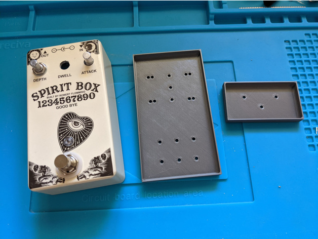
That's a lot of attention to detail out your holes.. I commend your patience.. I use this perfect 3d printed drill guide with a spring loaded punch to mark hole layout.... Then I use an 8" drill press to drill out my enclosures in less than 5 minutes worth of work..
 
I'd love to use a template, but I like using different knobs, typically big oversize ones and I'll move the holes around to get them just how I want them.

I'm working towards identifying trends as far as what knobs I like, and I'll likely build a few templates, one for each size enclosure x each knob style. I'd like to be able to scale my output, but I don't want the attention to detail to suffer.
 
Back
Top