
Big Monk
Well-known member
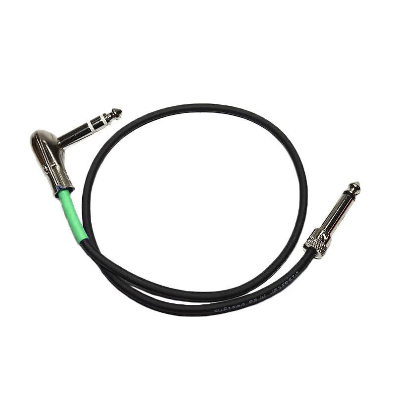
Just looking for a peer check on my breakdown of this simple cable:
 www.disasterareadesigns.com
After getting my new switcher hooked up, I noticed a small 1-2s lag time for the trigger outputs to engage my favorite settings on my Flint and El-Cap. Not a huge deal as I’m a bedroom basher.
In a recent Strymon thread over at TGP, I learned that with other switchers, such as the Boss ES-8, this lag is more pronounced and is a result of the microcontroller based switching initiating the trigger switches.
The above cable incorporates a pull up resistor to mitigate this lag by not allowing the digital input/output of the trigger to “float”. At least that’s how my ape brain interpreted it.
I’m more than willing to buy one of thy else and open it up so that I can then make 4 of these cables to have and use, but my thought process on how they are constructed is as follows and I could save myself the $24 with shipping:
1.) For favorite or tap tempo operation, the Strymon pedals only use the conductor attached to the ring of the TRS jacks on either end to supply power to the external switch LED.
2.) Since Disaster Area describes these having a pull-up resistor rather than pull-down, my assumption is that they are connecting the resistor to power at the Strymon.
So, short story long: It seems that if I have a TRS plug on one side with an appropriate value resistor attached from tip to ring and attach a 2 conductor wire to the other other end terminating at a mono plug, then I have essentially recreated this cable.
Any thoughts?
MJ-STT Strymon Tap Tempo Cable — Disaster Area Designs
Custom-made cable to connect standard tap tempo outputs to Strymon pedals.
www.disasterareadesigns.com
After getting my new switcher hooked up, I noticed a small 1-2s lag time for the trigger outputs to engage my favorite settings on my Flint and El-Cap. Not a huge deal as I’m a bedroom basher.
In a recent Strymon thread over at TGP, I learned that with other switchers, such as the Boss ES-8, this lag is more pronounced and is a result of the microcontroller based switching initiating the trigger switches.
The above cable incorporates a pull up resistor to mitigate this lag by not allowing the digital input/output of the trigger to “float”. At least that’s how my ape brain interpreted it.
I’m more than willing to buy one of thy else and open it up so that I can then make 4 of these cables to have and use, but my thought process on how they are constructed is as follows and I could save myself the $24 with shipping:
1.) For favorite or tap tempo operation, the Strymon pedals only use the conductor attached to the ring of the TRS jacks on either end to supply power to the external switch LED.
2.) Since Disaster Area describes these having a pull-up resistor rather than pull-down, my assumption is that they are connecting the resistor to power at the Strymon.
So, short story long: It seems that if I have a TRS plug on one side with an appropriate value resistor attached from tip to ring and attach a 2 conductor wire to the other other end terminating at a mono plug, then I have essentially recreated this cable.
Any thoughts?