Sanity check - DC filtering

MBFX

Well-known member
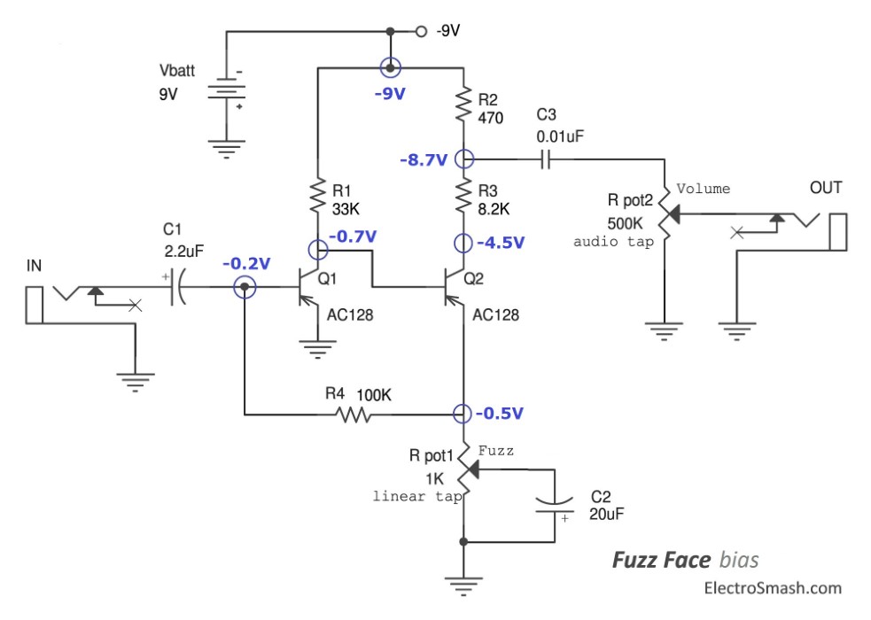
@Chuck D. Bones and @BuddytheReow helped me troubleshoot a Ge Fuzz Face build, and it's up and running on my breadboard! It isn't terribly fuzzy though - more of a dirty boost. I want to make use of these $10/piece transistors, so I'm going to stick a booster in front of them and make a Tone Bender. Simple, right?

I just want to make sure I am thinking of this correctly. I am using PNP Ge transistors with the Fuzz Face circuit "upside down", connecting the schematic grounds to power and vice versa, so I can use the PNP transistors with a center-negative power supply. I only have NPN Si available to make the input stage, so my plan is to pretend I am building two pedals. Each circuit will be complete, with its own input and output cap. The booster circuit and Fuzz Face circuit will be discrete but on the same board, with the output of one feeding into the input of the other. This should eliminate any problems using both PNP and NPN transistors on the same board.... right?

Have I accounted for the variables that would preclude using NPN and PNP transistors on the same board? I think that making them both use a center-negative power supply and isolating the circuits with their own input/output caps is a good start, but I don't know enough to know what else might be affected by doing this.
 
Before going this route I would look a little harder at your breadboarded circuit. Your germ fuzz face should be plenty fuzzy!
 
Before going this route I would look a little harder at your breadboarded circuit. Your germ fuzz face should be plenty fuzzy!

Went through it a bunch of times. The volume and fuzz pots do what they should, it's loud as shit, and it's really fuzzy with low notes, but high notes are more clean. Chuck said that's why many people choose pre-matched Ge transistor sets, which I will eventually do. I'm thinking goosing the front end will give me what I want, at the expense of the volume knob control.

I actually have it laid out right now! I used an Electra circuit for the input boost, minus the clipping diodes. Voltage divider was adjusted to lower the output (I can't believe I know how to do that now!!!). It's switchable, because why not? I'll post a photo later
 
What are the voltage on the Fuzz Face circuit on the breadboard?

What are the hFE and leakage values on the transistors?

A germanium fuzzz face, biased properly, should roar.

I wouldn’t go adding anything until you know why it isn’t.
 
What are the voltage on the Fuzz Face circuit on the breadboard?
Measured just now, 8:30AM PST. Wildly different values from last night - it was cold!

Q1 - 1970's AC128, ~70hFE, ~300µa leakage
Q1-B: 8.99
Q1-C: 6.47
Q1-E: 9.07

Q2 - 1970's GT402I, ~140hFE, ~300µa leakage
Q2-B: 6.47
Q2-C: 4.06
Q2-E: 6.64

This schematic, replacing the 8.2K resistor with a 10K trimpot, the fuzz pot with a 1K resistor, and the fuzz capacitor with a 4.7µF:

1698075441967.png
All caps are electrolytic, positive side looking at voltage and negative at ground. I adjusted the trimpot until Q2-C was ~4.5. What can I do to adjust the bias on Q1? I'm pretty sure that's the problem - Q1-C is too high. No idea what to do about it though.

Putting a booster before it helped, somewhat. I was curious and the parts were on my desk, so I did it. Switchable and DC isolated! It didn't affect the other circuit when I checked.
 
Right now I have the booster disconnected, so that can be ignored. Schematic for FF is above - I shouldn't need to flip the caps around because I'm powering it upside-down to use a center-negative supply, according to Jack's writeup on it
 
Check your connections on Q1. Those values are FUBAR.

Breadboards are notoriously finicky, particularly with thin leads on the components.

Also make sure all your polarized stuff is correct. Why don't you run it like a normal PNP Fuzz Face with a battery to get everything dialed in then flip everything?

Start by fixing what's wrong first and getting it to run normally on a breadboard.
 
I have a power supply, but no 9V batteries. I also don't have any barrel connectors to make a center-positive cable at the moment.

Everything seems to be connected correctly, and I measured each resistor out of circuit to verify values.

What should Q1 values look like, so I have a point of reference?

EDIT: It looks like you want <2VDC at Q1-C; does that sound correct? Finding definite answers to these things is like pulling teeth sometimes when you don't know quite enough to articulate your questions properly... Thanks for everyone's patience and help. I tried simply lowering the 33K resistor value a lot to see what would happen, and it made the circuit not work. Switching back to 33K made it a very loud dirty boost again. I'm going to work, so I'll check on this again tomorrow.
 
Last edited:
I have a power supply, but no 9V batteries. I also don't have any barrel connectors to make a center-positive cable at the moment.

Everything seems to be connected correctly, and I measured each resistor out of circuit to verify values.

What should Q1 values look like, so I have a point of reference?

EDIT: It looks like you want <2VDC at Q1-C; does that sound correct? Finding definite answers to these things is like pulling teeth sometimes when you don't know quite enough to articulate your questions properly... Thanks for everyone's patience and help. I tried simply lowering the 33K resistor value a lot to see what would happen, and it made the circuit not work. Switching back to 33K made it a very loud dirty boost again. I'm going to work, so I'll check on this again tomorrow.

Q1c should be around 0.5 vDC.
 
Right now I have the booster disconnected, so that can be ignored. Schematic for FF is above - I shouldn't need to flip the caps around because I'm powering it upside-down to use a center-negative supply, according to Jack's writeup on it
I'm confused--you said you were using two circuits (a PNP and an NPN), each with one transistor, so you've modified the above schematic, right?
 
I have a power supply, but no 9V batteries. I also don't have any barrel connectors to make a center-positive cable at the moment.

Everything seems to be connected correctly, and I measured each resistor out of circuit to verify values.

What should Q1 values look like, so I have a point of reference?

EDIT: It looks like you want <2VDC at Q1-C; does that sound correct? Finding definite answers to these things is like pulling teeth sometimes when you don't know quite enough to articulate your questions properly... Thanks for everyone's patience and help. I tried simply lowering the 33K resistor value a lot to see what would happen, and it made the circuit not work. Switching back to 33K made it a very loud dirty boost again. I'm going to work, so I'll check on this again tomorrow.
I'd recommend checking out this ElectroSmash article on the Fuzz Face. Lots of useful stuff, including this schematic showing the voltages at key stages of the circuit:

fuzz-face-bias-small.jpg

I'd view those voltages as a starting point; I personally like -5.25v on Q2c, but if your values aren't anywhere close to the ones here, then there's something wrong with how you laid out the circuit. Sharing a picture of your breadboard would be helpful to pinpoint the issue.
 
I'm confused--you said you were using two circuits (a PNP and an NPN), each with one transistor, so you've modified the above schematic, right?

I have two PNP Ge transistors to make a fuzz face (literally exactly two, one of each model). They're expensive, so I didn't buy more. Since it isn't very fuzzy, I figured making a very large boost to the input would make it do something closer to what I wanted. My original question was, if I build two discrete circuits on a single breadboard with their own input and output DC filtering caps, would they function separately and not care about which transistors the other was using. Through experimentation, I found the answer to be yes!

However, that devolved into a discussion about the FF circuit itself, with a question about voltages at different points on the transistors
 
  • Like
Reactions: spi
I'd recommend checking out this ElectroSmash article on the Fuzz Face. Lots of useful stuff, including this schematic showing the voltages at key stages of the circuit:

fuzz-face-bias-small.jpg

I'd view those voltages as a starting point; I personally like -5.25v on Q2c, but if your values aren't anywhere close to the ones here, then there's something wrong with how you laid out the circuit. Sharing a picture of your breadboard would be helpful to pinpoint the issue.

Thanks for this. Those voltages are not possible using the "upside down" schematic from muzique.com, since all grounds within the bounds of the filter caps are connected to power. That gives me 9VDC at Q1-E, etc. However, we are talking positive voltage, not negative, since the power supply is not flipped.
 
Thanks for this. Those voltages are not possible using the "upside down" schematic from muzique.com, since all grounds within the bounds of the filter caps are connected to power. That gives me 9VDC at Q1-E, etc. However, we are talking positive voltage, not negative, since the power supply is not flipped.
In that case shouldn't you be measuring voltage with reference to 9v instead of ground? The numbers should still match up, e.g.Q1e will be 0v relative to the 9v supply.
 
It's kind of curious that not many pedal makers have adopted this way of wiring the circuit. It seems most reverse power supply with a charge pump. I wonder why?
 
It's kind of curious that not many pedal makers have adopted this way of wiring the circuit. It seems most reverse power supply with a charge pump. I wonder why?

I've been able to breadboard all sorts of stuff in the last few months, including a Distortion+, a simple delay, and others. I can't seem to get this working right. It's probably just easier to use the charge pump and not have to think about negative voltage, etc! At this point I've sunk in enough time and learned enough from the project that I want to see it through, and use my notes as a guide for future me.
 
  • Like
Reactions: spi
Back
Top