Thewoodenone
New member
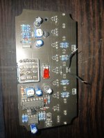
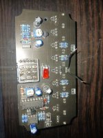
I am not getting any lighting up of the LEDs. I am sure that the anode and cathode are correctly oriented according to the board layout. I am getting a low voltage reading on the anode of around .07 but three is 9.45 at the dc input. I have reflowed everything. Can you all see anything I am missing or a misplaced part?
")