MichaelW
Well-known member
I'm not sure if this really belongs in the "Troubleshooting" forum but I thought I'd start here.
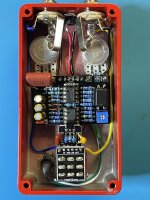
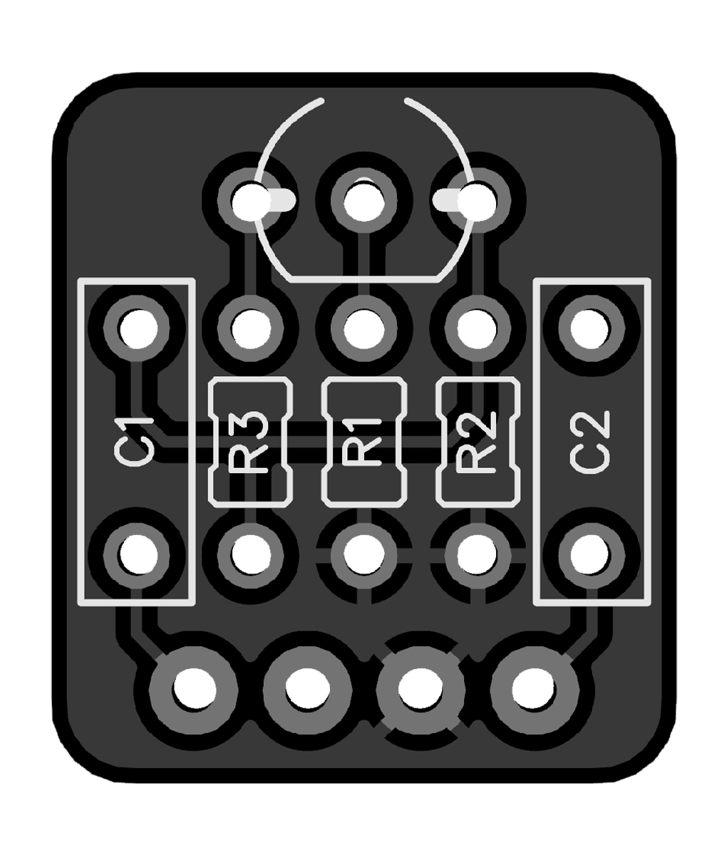
I incorporated the Simple JFET Buffer board from PPCB into my latest build, the Constrictor compressor. This was more or less an experiment in using a unity gain buffer that I figure could be easily reversed if I didn't like it.
I'm not sure I wired it correctly and it's got some unintended consequences with the way I wired it.
I could not find a lot of information about how best to use this board and a search of the forum didn't really make things much clearer on how others have this wired.
What I was intending was a buffered effect that the buffer turned on and off with the effect. In an attempt to keep the wiring as clean as possible, I decided to install the buffer board inline between the footswitch and the main PCB. If I'm understanding this correctly, in this configuration the buffer is before the circuit and "should" take advantage of the power filtering and polarity protection of the main board.
I have the "In" from the buffer board wired between the "In" pads of the main board and 3PDT board.
I have the "out" from the buffer board wired between the "out" pads of the main board and 3PDT board.
Same goes for the Ground pad.
For 9v power I have the 9v pad on the buffer board wired between the SW pads between the main board and 3PDT board. (I think this might be where some of my problem comes from).
The rest of the 3PDT board is wired as usual.
So the two issues I am having is:
1) The status led is always on. When I turn the effect on it gets brighter but even when the effect is off the led is on.
2) I'm getting an annoying pop when turning the pedal on and off. I found a post where @Big Monk added RPD's to address this but wasn't clear how he added them or where.
I am open to suggestions of a better way to wire this board (or someone to tell me what I did wrong...


