So the pedal gets bypass on the auditorium platform but when you engage the switch, you just get a loud pop. Maybe someone can see something I’m missing here I tested every resistor and cap and potentiometer. I’m hoping it’s something simple but right now it gets nothing on the auditorium platform except that loud pop and the light of course comes on.
Just to complete this thread. Excellent circuit- it can shape your tone and provide clean boost. Robert found a bad cap in my build and that was the key.
I would mark this solved, but I am not sure how. Maybe an admin could help with it.
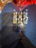
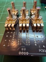
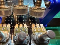
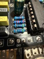
Here’s a pic of under the potentiometers. I should mention I’m not sure how to test an electrolytic capacitor and there’s only one in the building and it’s a 100 U. When I measure it with my multimeter, it seems to have the similar readings as other ones in my inventory.
Not sure how to check traces. But can you also tell me what socket I should use? I am rather new at this and put together a few Stewmac pedals which utilized this type of socket.
Not sure how to check traces. But can you also tell me what socket I should use? I am rather new at this and put together a few Stewmac pedals which utilized this type of socket.
Thanks for that. Oddly enough one time I built a pedal and accidentally put that type of socket and thinking I had made a mistake. I removed it. In removing it, I rendered the board useless. The more you know the more you know the more you know.
What you want to confirm is that each pin of the IC is making proper contact with the underside of the board. Tricky without a multimeter with that option. So failing that, check that each pin of the socket has sufficient solder and that you haven’t missed any altogether. Feel free to ask me how I know…
Thanks for that. Oddly enough one time I built a pedal and accidentally put that type of socket and thinking I had made a mistake. I removed it. In removing it, I rendered the board useless. The more you know the more you know the more you know.
I use that type of socket in all of my builds and have never had an issue. I am in the minority around here, but I personally don't like the machined sockets.
Just make sure the IC is seated firmly.
Not to sound like a broken record, but where did you get your TL074s?
I use that type of socket in all of my builds and have never had an issue. I am in the minority around here, but I personally don't like the machined sockets.
Just make sure the IC is seated firmly.
Not to sound like a broken record, but where did you get your TL074s?
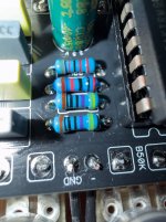
These two are from stomp box. Actually swapped out the ones from the picture thinking that they may be an issue and put two different ones that were from stomp, but it had no effect on the pedal. As you know, the most discouraging thing is to work on something for many hours and then. Get nothing. I made such a great enclosure for this pedal
These two are from stomp box. Actually swapped out the ones from the picture thinking that they may be an issue and put two different ones that were from stomp, but it had no effect on the pedal. As you know, the most discouraging thing is to work on something for many hours and then. Get nothing. I made such a great enclosure for this pedal
Those should be trustworthy then... They looked a little suspicious to me at first, but after comparing to the ones I have here (direct from TI) they look similar.
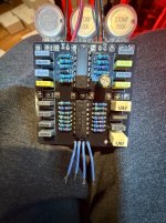
Let's make sure you don't have any solder bridges between the pins of your sockets.
Set your DMM to continuity mode, no power applied to the pedal, all pots turned to noon. You can do this with the ICs installed or removed.
Do this for each of the ICs, one at the time.
Starting with one lead on pin 1, use the other lead to sequentially probe each other pin of that IC. (2, 3, 4, etc) all the way around.
Make a note of any two pins that have continuity.
Now move your lead to pin 2 and repeat (3, 4, 5, etc) You don't have to back up to pin 1, we've already checked that one in the first step.
Now move your lead to pin 3 and repeat (4, 5, 6, etc) Again, you don't have to back up to pin 1 or 2.
Doing it this way saves time because you don't have to step backwards.
The upper IC should have continuity between pins 1/2, 6/7, 8/9, and 13/14.
The lower IC should have continuity between pins 1/2, and 13/14.
Any other pins with continuity should be investigated.
One thing I can't stress enough is to be patient and don't start ripping parts off of the board until you're fairly sure.
Also, aside from semiconductors (ICs, transistors, etc) from shady sources (Amazon, eBay, Alibaba, AliExpress, etc), it's not extremely common to have a defective new component. It's almost always something else..... bad solder connection, incorrect value, something making contact where it shouldn't, etc...
I have almost never had an issue turn out to be a defective component in a new build. It happens, but it's almost always some other issue.
This sounds silly, but make sure you don't have the cables hooked up backwards. (Guitar plugged into the output)
You'd be surprised how many times this happens, even to folks who have been building for years.
These two are from stomp box. Actually swapped out the ones from the picture thinking that they may be an issue and put two different ones that were from stomp, but it had no effect on the pedal. As you know, the most discouraging thing is to work on something for many hours and then. Get nothing. I made such a great enclosure for this pedal
It's not over yet. There's always going to be a reason it's not working - we just need to find out what that reason is. We will find it, it's just a matter of time.
The popping noise means DC is in the signal path somewhere. We just have to find out why. A common place for this to happen is at the IC socket, so start there
I use that type of socket in all of my builds and have never had an issue. I am in the minority around here, but I personally don't like the machined sockets.
I share this hot take. As long as you straighten the legs of the IC enough, leaf sockets are quite easy to use.
I'm more inclined to just solder ics at this point