comradehoser
Well-known member
- Build Rating
- 5.00 star(s)
Upon @HamishR 's enthusiastic suggestion (thanks, bud!), I had a go at this circuit. The breadboarding was super dumb, but I struggled through it, loved the Marshall Big Rock sound it gave, and of course I had to try to PTP the thing.
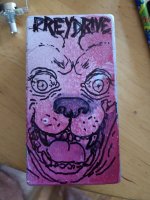
This time, though, I had a concept and did graphics and drilling as you should before assembling PTP. I drew upon my dog Marx's manic moments (he was a red nose pit bullterrier, RIP at 17). The paint was supposed to be red splatter, turned more pink frosting. I edited the drawing as well to make it more aggro as the original looked kinda derpy.
The assembly was painstaking but normal for PTP. 9v line on the left, ground on the right. Base layers first, and I did tie ins and components for all pots (except I forgot to tie volume 1 to ground, d'oh. Didn't discover that until I plugged in).
Started at the ins of the circuit and just moved through it. The 9v line ended up being a bit odd, but I wanted to respect what the circuit sees in order.
Most of the circuit was situated through trial and error, constructed out of box around the transistor arrays, and then connected and installed. I had to employ verticality to relate everything correctly. Waaaaaay easier than breadboarding. My daughter said it looked well organized. I guess that means it's OK. Not quite as aesthetic as my last build, the OK Doomer, but I'm pretty happy with it.
Dynamic, amp-like tones, can get beautiful decay with the right transistors and biasing. It never really gets clean, can get tite and chuggy with a bass cut, but generally stays more in the land of warm middy overdrive than the animals/diamond peak which is a bit more angular and easily able to fuzz out. Like I said before, gain at 10 bass/treble noonish you can cop the back in black tone almost exactly. You can also find some Rocket from the Crypt/ Drive like Jehu/Hot Snakes in there too. Very satisfying and fun to play.

original take
modified
with knobs and LED concept
Aaaaaa the light... transistors! (That wasn't on purpose). Used low-gain silicon transistors from a stash so very kindly provided by enabler supreme @jwin615. 48 hfe at Q2 (MPS 2369 the lower one) and a 63 hfe (Motorola? 2N5330 the higher one) at Q3. I don't know if the ascending hfe order matters so much or at all as in JFET circuits, but I thought it couldn't hurt and it didn't. I tried a bunch of combos, I even installed 20-something hfe metal can transistors backwards by accident (collector-base-emitter reversed). I had a hard time getting the circuit to sound bad even with my mess ups, but this combo sounded best and probably closest to original intent. I contemplated putting the backwards transistors on a switch because I like the openness and clarity they gave, but then I remembered this is a PTP in a 125b with 4 tie ins, so I would be rolling the dice on space and complexity. So, no.
Here's what I wrote elsewhere: "I noticed were some trends: higher gain transistors as well as higher bias works, but it makes the circuit less organic/amp-like and more synthetic/ effect-like. (Also, one of my transistors at higher gain was creating amp-like feedback). The 4.35 [ he later settled on 4.6, actually] bias for Q3 collector Chuck identified is a great baseline.
To me, I like a lower Q2 because it gives a nice organic (maybe uneven or asymmetric?) quality to the distortion decay which sounds good to me, and doesn't lead to sudden crackly cut off to the clipping with gain at max."
I might mess with the bias a bit since I probably bumped it on installation--there are some artifacts I don't like as much with treble up and gain down. The bias does affect the nature of the decay of the breakup and I really like a gradual decay. Too subtle and precious an adjustment? What can I say? I like what I like.
Here it is with its big bro/sis the Diamond Peak/Animals
Still looks like amateur town with wobbly and unstraight lines. @ErikS better do a PTP soon so's people can see proper nice lines.
A look at the verticality
And another view
This time, though, I had a concept and did graphics and drilling as you should before assembling PTP. I drew upon my dog Marx's manic moments (he was a red nose pit bullterrier, RIP at 17). The paint was supposed to be red splatter, turned more pink frosting. I edited the drawing as well to make it more aggro as the original looked kinda derpy.
The assembly was painstaking but normal for PTP. 9v line on the left, ground on the right. Base layers first, and I did tie ins and components for all pots (except I forgot to tie volume 1 to ground, d'oh. Didn't discover that until I plugged in).
Started at the ins of the circuit and just moved through it. The 9v line ended up being a bit odd, but I wanted to respect what the circuit sees in order.
Most of the circuit was situated through trial and error, constructed out of box around the transistor arrays, and then connected and installed. I had to employ verticality to relate everything correctly. Waaaaaay easier than breadboarding. My daughter said it looked well organized. I guess that means it's OK. Not quite as aesthetic as my last build, the OK Doomer, but I'm pretty happy with it.
Dynamic, amp-like tones, can get beautiful decay with the right transistors and biasing. It never really gets clean, can get tite and chuggy with a bass cut, but generally stays more in the land of warm middy overdrive than the animals/diamond peak which is a bit more angular and easily able to fuzz out. Like I said before, gain at 10 bass/treble noonish you can cop the back in black tone almost exactly. You can also find some Rocket from the Crypt/ Drive like Jehu/Hot Snakes in there too. Very satisfying and fun to play.

original take

modified

with knobs and LED concept

Aaaaaa the light... transistors! (That wasn't on purpose). Used low-gain silicon transistors from a stash so very kindly provided by enabler supreme @jwin615. 48 hfe at Q2 (MPS 2369 the lower one) and a 63 hfe (Motorola? 2N5330 the higher one) at Q3. I don't know if the ascending hfe order matters so much or at all as in JFET circuits, but I thought it couldn't hurt and it didn't. I tried a bunch of combos, I even installed 20-something hfe metal can transistors backwards by accident (collector-base-emitter reversed). I had a hard time getting the circuit to sound bad even with my mess ups, but this combo sounded best and probably closest to original intent. I contemplated putting the backwards transistors on a switch because I like the openness and clarity they gave, but then I remembered this is a PTP in a 125b with 4 tie ins, so I would be rolling the dice on space and complexity. So, no.
Here's what I wrote elsewhere: "I noticed were some trends: higher gain transistors as well as higher bias works, but it makes the circuit less organic/amp-like and more synthetic/ effect-like. (Also, one of my transistors at higher gain was creating amp-like feedback). The 4.35 [ he later settled on 4.6, actually] bias for Q3 collector Chuck identified is a great baseline.
To me, I like a lower Q2 because it gives a nice organic (maybe uneven or asymmetric?) quality to the distortion decay which sounds good to me, and doesn't lead to sudden crackly cut off to the clipping with gain at max."
I might mess with the bias a bit since I probably bumped it on installation--there are some artifacts I don't like as much with treble up and gain down. The bias does affect the nature of the decay of the breakup and I really like a gradual decay. Too subtle and precious an adjustment? What can I say? I like what I like.

Here it is with its big bro/sis the Diamond Peak/Animals

Still looks like amateur town with wobbly and unstraight lines. @ErikS better do a PTP soon so's people can see proper nice lines.

A look at the verticality

And another view
Attachments
Last edited:

