SOLVED Softii - first build... no sound 🙃

Petethefuzz

Active member
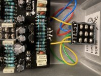
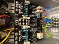
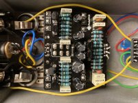
Hi guys. Total n00b here. Just finished my first build. Maybe I took on to much, but I fell in love with the SFT so I wanted a clone. With help online/facebook I have tested that the switch works (multimeter buzz test). LED works. I’m very new
to electronics/circuits and even the multimeter. I have seen this kit in the forum - has anyone had the same issue? Doesn’t work out of the enclosure either, so it doesn’t appear to be pots making a short or something like that. I had to wire one of the transistors cause the socket
Was broken. I bought it as a kid from musikding.de

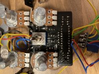
If you would be so kind to give me instructions on what and how to test, maybe with the multimeter, I’d really appreciate it. Please feel free to address me as a total beginner. If you feel like you are writing to a toddler your probably doing great 😀 B285A3C2-B7FD-41FC-B13B-7C5CC3FB5D32.jpeg 874E7980-35C9-4A59-8AF9-A8AA4267D1B9.jpeg 8A45A905-060C-43B9-983E-0364CD9C9CFB.jpeg 7D9C8013-13A2-4FB8-BF78-26B10A32F2B9.jpeg 7EDB496C-114E-4C1F-8ED2-95948F2E2C78.jpeg
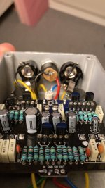
 
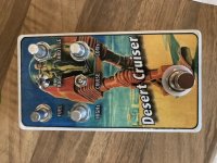
I am love with the artwork.

First thing is to check voltages to make sure that power is getting where it needs to. Put the black lead from your multimeter on a ground point on the board, and set it to a DC voltage setting around 20V. Use the red lead and probe each of the transistor leads. Given that they are in sockets I would try and measure on the actual component lead to make sure there is a good connection with the socket. For consistency we will call the pins from left to right in your bottom photo above as 1 2 3.
 
Thanks you so much! I’ll get back to you with the readings asap 😀👍... what is a ground point on the board though? Could it be where the pcb says gnd... where the switch is wired?
 
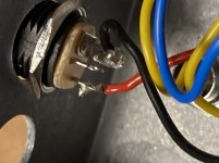
Ground could be a few points on the board. GND cable is one of them. Or, to bypass the board altogether, place the black tip on the larger metal clip of the power plug (I believe it is where the black wire is on your pics, but they are a little blurry).

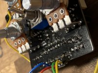
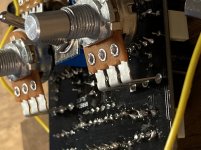
Also if you can take the circuit out of the box and post pics of the underside, that may help us find any cold solder joints or dirty board that may need cleaning.

Does bypass work? Check to make sure the cables are plugged into the right jack. If they're in backwards bypass will work and the circuit will not produce sound.
 
Take a photo looking straight down on the board so we can read all of the resistors.
On the transistors, measure only the middle pins. That will tell us what we need to know.
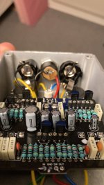
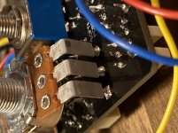
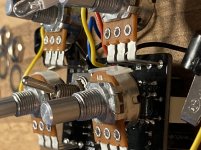
Make sure that the bodies of the pots under board are not contacting any of the circuitry.
Where did you buy your transistors?

Nice artwork!
 
Update - bypass works and I’ve flipped the jacks but no luck. Got help online to check the switch so it should be fine. Ive put rubber pads on the pots so they don’t appear to touch circuit. I’ll post pics asap as requested. I do remember it being a little dirty some places after soldering. Is it some vapors from the solder that sticks on the pcb? Anyway here are my measurements. Q5 acted weird:

Q2 8,84V
Q1 1,28V
Q5 1,25V (and slowly dropping!?)
Q6 5,61V
Q4 5,62V
Q3 1,47V

Glad you like the artwork. At least that worked out ok 😂
 
Q1 - good
Q2 - not good recheck this one
Q3 - good
Q4 - good
Q5 - bad connection? lead(s) may be loose in the socket.
Q6 - good

That funk on the board is flux residue. The solder is hollow and has resin in the middle to act as a cleaner and a glue. Was the board with alcohol.
 
Q1 - good
Q2 - not good recheck this one
Q3 - good
Q4 - good
Q5 - bad connection? lead(s) may be loose in the socket.
Q6 - good

That funk on the board is flux residue. The solder is hollow and has resin in the middle to act as a cleaner and a glue. Was the board with alcohol.
Thanks I’ll check the socket. Maybe I should just drop the socket and wire the transistor directly? I’ll get hold of alcohol as soon as stores open up again. What should Q2 read ?

If the Flux touches the capacitors will it turn in to a time machine 🤪?!
 
Funny how Q2 is the only one I’ve soldered directly without a socket by the way. I swapped them all during testing before I soldered it so I don’t think it’s the transistor.
 
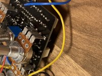
Some more pictures. Just tried it again out of the enclosure. The volume pot has an effect as I can hear it chance the character of the low hum that passes. Got a small pop when I tried the tone switch so it appears to be alive as well. I know my solder are a bit to long and I’ll trim them but nothing appears to be touching anything. If I want to test it without the bypass switch how do I do that?
FYI Q2 stays stable at around 1,2 V after it drops a bit.

3C442C1C-2118-48F2-B9D4-11E66F830DFA.jpeg 88CA78C1-EC17-470D-8F48-2C8122C97ED8.jpeg EC008EBF-7DA3-480F-B601-7EC48151A4E9.jpeg 245F79C0-577F-4983-9C05-F6DD2C65BDF3.jpeg 93291DEC-44C4-4027-93A3-FA0E715F2E52.jpeg 023007A2-5258-49D9-B012-3AB613B7F1C0.jpeg
 
Yeah it’s just crossing, got me confused. You should def get some isopropanol and clean that board though. Makes it easier to look for cold joints. Have you done a reflow?
I’ll get to the cleaning asap. I’ve reflowed a bit but the two pots are in the way. I find them difficult to desolder... is it possible?
 
Just reflowed everything. Still no luck. Will cleaning the board potentially fix anything or just make it easier to check out? I’ve used the multimeter on the resistors and I think they check out fine. Anything else I can check?
 
Back
Top