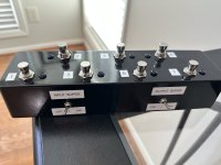
Something different (7 loop switcher)

mkstewartesq

Well-known member
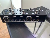
So, thanks to my pedal building addiction (of which you are all enablers), I had built so many pedals that I had filled up my current 10-loop switcher and had resorted to retiring about five pedals and then daisychaining certain others so that more than one pedal could use a single loop. This is 100% a “me” thing but it hurts my heart to see something I’ve built sitting on a shelf and I’m far too lazy to swap pedals out on the board frequently.

So I decided to move all of my dirt pedals (both those currently active on the board and some that have been retired to my shelf) onto a separate smaller pedalboard and run those off of a single loop on my main switcher (I really don’t ever stack dirt pedals so only one would be active at any given time ). This required an additional switcher and, because I am cheap, I didn’t want to buy a second one. So I found several different plans online for switchers from 2 to 4 loops, selected the best one (some of the plans out there are reported as not working or having issues) and decided to build it with seven loops so that I would have room to grow. No master bypass because that function will be accomplished on the main loop switcher.

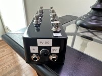
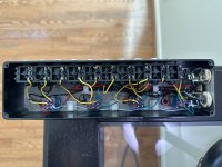
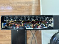
There were some minor glitches. Because this switcher and its board will be sitting in a corner, I put the input and output on the same end; that feature, along with the fact that I was having a couple more loops than most diagrams contemplated and was staggering things into two rows made things a bit of a brain teaser to ensure that I didn’t wire up something backwards or out of order. But it’s complete, all of the loops work, and now I’m on to the next circle of hell which is cutting and soldering 14 patch cables to feed this loop switcher.

Thanks for looking.

Mike
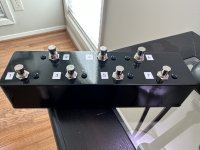
IMG_9381.jpeg IMG_9383.jpeg IMG_9382.jpeg IMG_9386.jpeg
 
Very cool. Do you see the need to add a buffer to your chain?
Not yet. There may be a possible need for that once I really start filling up all the loops but I just completed the switcher this AM. I put a couple of pedals in the first and last loop to at least get a sense if there was signal loss with the signal running through all 7 3PDTs to the output jack and didn’t notice any issues but that doesn’t mean that issues won’t arise whenever I really load this whole thing up on all of the loops. But – so far so good.

Mike
 
I built a BYOC 8 switch programmable looper last year. I like it pretty well. I’d like to have to ability to turn one loop on without having to first switch one off. That would be a great feature.
 
I built a BYOC 8 switch programmable looper last year. I like it pretty well. I’d like to have to ability to turn one loop on without having to first switch one off. That would be a great feature.
You mean flip-flop functionality (where you can assign loops to basically be exclusive as to certain other loops so that turning it on will automatically turn one or more of the other loops off)? I have that on my main switcher (GigRig Quartermaster 10) and it’s quite handy. Because I don’t normally stack dirt pedals, I set it so that kicking on any one dirt pedal would automatically turn off all of the other dirt pedals. Now that I’ve moved all my dirt pedals to this DIY switcher, I’m going to miss that functionality (I believe it’s possible to do flip-flop in something like what I built, but you have to get into stuff a lot more complicated than I understand to make it work. I’m just not up on arduino, etc.).

Mike
 
Very cool. Do you see the need to add a buffer to your chain?

Glorious! I built a similar 5 loop switcher a while back. I did end up adding a switchable PPCB JFET boost to the beginning and end of mine, just for fun.

OK, well, after A/B-ing how each pedal on my regular switcher against how it sounds on the one I built, there is a definite difference. When pedals are plugged into the new switcher, they sound a fair amount weaker. My boosters basically max out at unity volume (rather than, you know, boosting), and my other drives sound like they’re not getting hit as hard by the signal as they do when they are on the main switcher. This is true whether the pedal I am testing is the only pedal connected to the new switcher or if there are multiple pedals connected to it.

Does this sound like something a buffer could remedy? If so, any thoughts on the best way for me to incorporate one into this build? Would it go at the front or at the end? (Sorry, as you can tell, I know absolutely zero about buffers).

Edit to add-my main switcher (a Gigrig) actually takes the entire loop out of the circuit if it is inactive. I get that the build I did above doesn’t do that, and it’s basically like seven true bypass pedals chained together even when all of the loops are off (in bypass). I assume that’s what’s possibly necessitating a buffer here?

Thanks,

Mike
Yessir
 
You mean flip-flop functionality (where you can assign loops to basically be exclusive as to certain other loops so that turning it on will automatically turn one or more of the other loops off)? I have that on my main switcher (GigRig Quartermaster 10) and it’s quite handy. Because I don’t normally stack dirt pedals, I set it so that kicking on any one dirt pedal would automatically turn off all of the other dirt pedals. Now that I’ve moved all my dirt pedals to this DIY switcher, I’m going to miss that functionality (I believe it’s possible to do flip-flop in something like what I built, but you have to get into stuff a lot more complicated than I understand to make it work. I’m just not up on arduino, etc.).

Mike
Yessir
 
The ppcb intelligent relay bypass has the flip-flop capacity of which ye speak. https://www.pedalpcb.com/product/relaybypass/

If you have a boss pedal kicking around, try putting it in between the two switchers (ie, between either the send or return of the quarter master and the in or out of the new switcher). If that helps with things you could tuck a little buffer circuit into the I or O (or both?) of your new switcher).
Thanks. I actually just posted a thread on this topic over in the general questions forum. I’m going to build a JFET buffer on stripboard today and try it on both the input and output to the switcher to see if it makes any difference. As I mentioned in that thread, this is a weird one (to me)– no real tone suck when all of the loops are in bypass (which I understood to be the traditional test for testing whether a bunch of daisychained true bypass needed a buffer), it’s just that the actual petals on each loop or weaker than they should be.

Thanks again!
Mike
 
You might also try sending signal through the switcher and using an audio probe to see if there's a particular spot in the wiring that's causing the problem. A bad switch, a cold solder joint, etc, in the wrong place could result in some lost signal. You've also got 14+ cables involved in this situation; that's another 28 or more places for something to have gone slightly wrong.

Your wiring looks tidy and the lengths seem pretty reasonable, but again there's also just going to be a whole bunch of uninsulated wire floating around in there which might be zigging when it wants to zag. Are the ground paths for the audio and the LEDs connected?
 
Are the ground paths for the audio and the LEDs connected?
Thanks. Each LED ground goes to lug 2 on a 3PDT, and then the 3PDT ground wire on lug 1 for each 3PDT is tied together with the grounds for the main I/O jacks (the bundles of black wires secured to the inner top of the enclosure). The pedal I/O jacks are grounded off of the main input jack.

M
 
Just updating to add that I built and installed an input buffer and an output buffer – both Cornish buffers, each controlled by a separate DPDT. Everything sounds great now.

For whatever reason, even though they are the exact same in every respect as far as I can tell, the second one I built sounded better than the first, especially when set up as the output buffer, so I think I’ll use that one most.

Mike

IMG_9416.jpeg IMG_9417.jpeg
 
Back
Top