I recently finished my SuperHeterodyne Receiver build, and thought I'd share a few things that could help others and save some time.
I used the Tayda printing and drilling services with a 1590XX enclosure, but I couldn't seem to find the coordinates for the holes to be drilled. The drilling service requires coordinates compared to the center point of the enclosure, so I ended up making a spreadsheet and translating the coordinates in my Illustrator file to that format.
This took a while to line up against the PedalPCB drill template, but here's what I came up with, and it worked great for me. I drilled out the LED hole a bit and used a 5mm LED, but I think all the other holes were the right size.
I believe Tayda can't drill the top mounted jack holes in their CNC machine, so I didn't include those here and just hand drilled them.
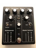
Attaching photos of how it turned out, plus the PDF file I used for the Tayda UV printing. It appears I can't share Illustrator files here, but happy to share that with anyone who wants to tweak my file for their own build.
This pedal is super wild and not going on my board, but still a fun pedal to play with and make some crazy sounds. I was a little intimated by the size of the board, but the build really wasn't bad. Not really that many components- just a lot of ICs.
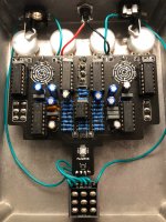
Be super careful when soldering the rotary switches. What I did was solder the Rate pot at the bottom of the board first, inserted the rotary switches, and then placed those three points into their respective holes in the enclosure as a guide. I still somehow soldered the rotary switches somewhat unevenly so they weren't totally flush with the board on the bottom. That's a bit hard to undo once you've soldered each in place in 9 places!
Luckily it wasn't wonky enough to cause any big issue, but don't do what I did.
Anyway, hope this is helpful to someone looking to build an SHR!
I used the Tayda printing and drilling services with a 1590XX enclosure, but I couldn't seem to find the coordinates for the holes to be drilled. The drilling service requires coordinates compared to the center point of the enclosure, so I ended up making a spreadsheet and translating the coordinates in my Illustrator file to that format.
This took a while to line up against the PedalPCB drill template, but here's what I came up with, and it worked great for me. I drilled out the LED hole a bit and used a 5mm LED, but I think all the other holes were the right size.
I believe Tayda can't drill the top mounted jack holes in their CNC machine, so I didn't include those here and just hand drilled them.
| Label | X From Center | Y From Center | Size |
| Square | -28.23 | 51.4 | 7 |
| Subharmonic | 0 | 51.4 | 7 |
| Oscillator | 28.24 | 51.4 | 7 |
| Level | 56.47 | 51.4 | 7 |
| L Selector | -14.11 | 26 | 7 |
| L Switch | -28.23 | 0.57 | 6 |
| R Selector | 42.35 | 26 | 7 |
| R Switch | 56.47 | 0.57 | 6 |
| Glide / Vibrato | 14.12 | 26 | 6 |
| Rate | 14.12 | 0.57 | 7 |
| LED | 14.12 | -35.68 | 4 |
| Footswitch | 14.12 | -54.13 | 13 |
Attaching photos of how it turned out, plus the PDF file I used for the Tayda UV printing. It appears I can't share Illustrator files here, but happy to share that with anyone who wants to tweak my file for their own build.
This pedal is super wild and not going on my board, but still a fun pedal to play with and make some crazy sounds. I was a little intimated by the size of the board, but the build really wasn't bad. Not really that many components- just a lot of ICs.
Be super careful when soldering the rotary switches. What I did was solder the Rate pot at the bottom of the board first, inserted the rotary switches, and then placed those three points into their respective holes in the enclosure as a guide. I still somehow soldered the rotary switches somewhat unevenly so they weren't totally flush with the board on the bottom. That's a bit hard to undo once you've soldered each in place in 9 places!
Luckily it wasn't wonky enough to cause any big issue, but don't do what I did.
Anyway, hope this is helpful to someone looking to build an SHR!