PedalBuilder
Well-known member
Here's my take on the Univox Super Fuzz. I was going for something a bit different and more flexible than the original, so I borrowed some features from the now discontinued Wattson Classic Electronics EFY-6. The main changes are adding an octave control that goes from no octave up to full octave up, replacing the tone switch with a potentiometer, and changing the bias resistors on the output stage to increase the output level above unity. I've included the schematic at the bottom of the post for anyone who's curious.
If I was redoing the board, I'd try to add some more room between the rows of 10µF capacitors and the solder pads for the Octave and Tone pots. I was able to solder everything without hitting the capacitors with the iron, but it was more of a challenge than I would have liked.
For the tone knob modification, I recommend using a B50k potentiometer, as there is a noticeable volume drop in the middle of the rotation when using a B100k. Using a potentiometer rather than a switch slightly reduces the depth of the mid-scoop and height of the mid-hump, and adds some great sounding in-between tones.
For the octave knob, I tried 10k and 5k potentiometers. The most dramatic change to the octave effect happens in the first 1kΩ of resistance; by about 4kΩ the octave effect is essentially gone. As a result, I went with a C5k to maximize the control over the octave intensity.
The Super Fuzz works best with transistors with an hFE between 110 and 140. Using higher gain transistors results in a mushy, less bassy tone, and lower gain transistors sound weak and (unpleasantly) gated. I used 2N5551 transistors from Tayda, which are dirt cheap and have gains between 120 and 135. For Q4 and Q5, I used a pair with identical hFE and VBE values to maximize the intensity of the octave up.
When I breadboarded the circuit, I originally tried germanium diodes, but on a whim I tried some 1N60P Schottky diodes that I bought from Tayda 12 years ago but had never gotten around to using. Compared to the germanium diodes, the Schottky diodes sounded more compressed and distorted, probably due to their lower Vf (0.22v at 1mA vs 0.33v at 1mA for the germanium diodes), and the octave overtones were slightly more pronounced. I preferred the sound of the Schottky diodes, so I kept them in the final build.
The enclosure is a white 125B from Tayda, UV printed with a gloss varnish.


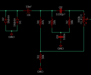
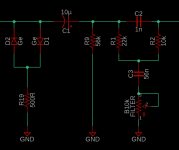
Here's the schematic, for those who are interested:

And here are the transistor voltages, at VCC = 9.27v.
Q1
E 0.134v
B 0.692v
C 5.568v
Q2
E 4.964v
B 5.568v
C 9.27v
Q3
E 2.971v
B 3.539v
C 6.31v
Q4
E 1.07v
B 1.664v
C 3.32v
Q5
E 1.07v
B 1.664v
C 3.32v
Q6
E 0.186v
B 0.762v
C 5.549v
If I was redoing the board, I'd try to add some more room between the rows of 10µF capacitors and the solder pads for the Octave and Tone pots. I was able to solder everything without hitting the capacitors with the iron, but it was more of a challenge than I would have liked.
For the tone knob modification, I recommend using a B50k potentiometer, as there is a noticeable volume drop in the middle of the rotation when using a B100k. Using a potentiometer rather than a switch slightly reduces the depth of the mid-scoop and height of the mid-hump, and adds some great sounding in-between tones.
For the octave knob, I tried 10k and 5k potentiometers. The most dramatic change to the octave effect happens in the first 1kΩ of resistance; by about 4kΩ the octave effect is essentially gone. As a result, I went with a C5k to maximize the control over the octave intensity.
The Super Fuzz works best with transistors with an hFE between 110 and 140. Using higher gain transistors results in a mushy, less bassy tone, and lower gain transistors sound weak and (unpleasantly) gated. I used 2N5551 transistors from Tayda, which are dirt cheap and have gains between 120 and 135. For Q4 and Q5, I used a pair with identical hFE and VBE values to maximize the intensity of the octave up.
When I breadboarded the circuit, I originally tried germanium diodes, but on a whim I tried some 1N60P Schottky diodes that I bought from Tayda 12 years ago but had never gotten around to using. Compared to the germanium diodes, the Schottky diodes sounded more compressed and distorted, probably due to their lower Vf (0.22v at 1mA vs 0.33v at 1mA for the germanium diodes), and the octave overtones were slightly more pronounced. I preferred the sound of the Schottky diodes, so I kept them in the final build.
The enclosure is a white 125B from Tayda, UV printed with a gloss varnish.


Here's the schematic, for those who are interested:

And here are the transistor voltages, at VCC = 9.27v.
Q1
E 0.134v
B 0.692v
C 5.568v
Q2
E 4.964v
B 5.568v
C 9.27v
Q3
E 2.971v
B 3.539v
C 6.31v
Q4
E 1.07v
B 1.664v
C 3.32v
Q5
E 1.07v
B 1.664v
C 3.32v
Q6
E 0.186v
B 0.762v
C 5.549v


