Thinking about Op Amps - help?!

dubspecialist

New member
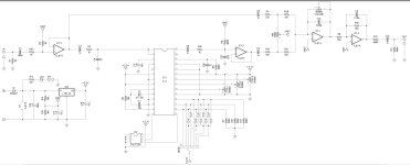
OK so I have a somewhat theoretical question to pose for anyone that is willing to help me. I am a n00b when it comes to this stuff so please forgive any glaringly obvious gaps in my knowledge. I am looking at the final two op amp gain stages in the Arachnid circuit and wondering if it could be possible to mod this for a pot controlled fuzz at the output stage of this circuit... I understand these two stages are 'inverting' gain stages and I assume that this is because stage 3 is a 'volume' control and op amp 'law' tells us "a disadvantage using non-inverting opamps is that they can’t have a gain less than 1, meaning that they can’t attenuate the signal" - hence the use of the inverting input at this stage and again at unity gain stage 4 to invert back (or am I mistaken?). I appreciate that through the use of diodes and a resistor (pot) we could achieve a fuzz circuit on this inverting gain stage in the arachnid BUT my problem is this... it seems the type of 'fuzz' or overdrive that I like is 'no clipping' or no diode boost/fuzz/overdrive (whatever you want to call it). I know this because I love the 'fuzz' sound on the DBA Echo dream 2 and the Plumes when set to mode 2 (pump the gain knob, reduce the level knob).

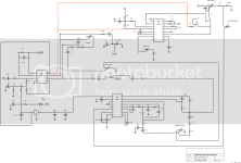
OK, long-winded I know, my question is this - could it be possible to change stage 3 and 4 of the Arachnid circuit to non-inverting and implement a no-diode drive with pot-control gain stage at one of these that felt akin to the 'fuzz' stage within the echo dream 2 or does the 3.3v power pose a problem here (lack of headroom / noisey maybe)? I have attached schematics for the arachnid and the ED2 for convenience. Any assistance would be greatly appreciated and apologies if I sound like a nincompoop.
 

Attachments

  • A_PCB_SCHEM.JPG
    A_PCB_SCHEM.JPG
    98.7 KB · Views: 14
  • B_PCB_SCHEMATIC.png
    B_PCB_SCHEMATIC.png
    226.7 KB · Views: 15
  • Like
Reactions: fig
It doesn’t need to be non-inverting. As it is, that volume stage gives, *I think*, a gain of around 6 with the Volume all the way up.

If you replaced the volume control with a larger pot, say 1Meg, you’ll have ten times that which would certainly be enough to overdrive the opamps to the point of fuzz. The issue then is the output would be way too loud, so I would suggest adding a conventional volume pot at the end of the circuit.

The 3.3v is not an issue as it’s only used for the FV1 chip, the rest of the circuit runs in 9v with 4.5v reference.

That Echo Dream schematic is a bit annoying to read since the opamp is represented by DIP symbol, but it looks like it does basically the same thing. Fuzz is a 1Meg pot in the feedback loop of and inverting gainstage.
 
Last edited:
Also, might I suggest alternatively that you build an opamp fuzz/distortion as it’s own thing. That will give you some more flexibility and allow you to use it with anything.

Listen to some clips of the Hovercraft Ionostrofear. PPCB has it too.
 
It doesn’t need to be non-inverting. As it is, that volume stage gives, *I think*, a gain of around 6 with the Volume all the way up.

If you replaced the volume control with a larger pot, say 1Meg, you’ll have ten times that which would certainly be enough to overdrive the opamps to the point of fuzz. The issue then is the output would be way too loud, so I would suggest adding a conventional volume pot at the end of the circuit.

The 3.3v is not an issue as it’s only used for the FV1 chip, the rest of the circuit runs in 9v with 4.5v reference.

That Echo Dream schematic is a bit annoying to read since the opamp is represented by DIP symbol, but it looks like it does basically the same thing. Fuzz is a 1Meg pot in the feedback loop of and inverting gainstage.

Amazing, thank you so much for the response! This all seems to make sense to me and is really encouraging. Would you mind just clarifying one thing for me - when you say 'it doesn't need to be non-inverting' could you clarify this a little? You are right re: the 6db, it definitely says this in the build doc/specs but I'm confused how the input signal could be on the '-' pin of the op amp but this doesn't necessarily mean it 'needs' to be non-inverting.

Thanks again for your help - it's seriously appreciated.
 
Also, to clarify I have inspected the data sheet for the Op Amp used in the ED2 and it appears to me that the signal is input on the '+' with feedback loop on the '-' which I assumed suggests a 'non-inverting' gain stage?
 
No problem!

What I mean is you don’t need to make it non-inverting to get it to fuzz, since you asked if you could mod it that way.

I’m still having a hard time with that Echo Dream schematic, but you are correct. The signal goes into the non-inverting input. This stage is essentially like the Plumes without the diodes.

Also just to clarify something else, though I know this doesn’t answer your questions: I derived the gain of 6 from the value of the resistors in the volume stage put into a calculator like this. All of those series and parallel 15k resistors in the front *I think* (I am by no means an expert on any of this, lol) equal 15k. Along with the 100k in the feedback loop (volume pot) gain is 6.666… If it was 1Meg (1000k), it’s 66.666…

Op amp gain isn’t db, it’s a straight up multiplication of the signal. Db is a logarithmic representation of this. And this is where my knowledge tops out. I haven’t touched the log button on a TI-84 since high school.

Thanks again, this has been so helpful. Yes, nice work, it would seem your math is dead on - as the documentation outlines a 6db boost at volume stage! EDIT: sorry I see your point here regarding op amp gain as multiplication not db. That makes perfect sense, so it may be coincidental that the product page states "... capable of up to 6db boost".

OK great, well that is very encouraging. I will experiment with leaving the input on the inverting pin but substituting in a larger value pot in the feedback loop of the 'volume' stage (probs better referred to as gain in this mod application) and then adding a volume pot at the end of the circuit after the unity gain stage. Will update with my findings here when I get a chance :)
 
Last edited:
So I have an update here and with that comes a follow up question. After experimenting with this build/mods to the opamp gain stages (with mixed result, mostly positive) I've decided that actually what I would like to do is simply add a variable boost to the input stage of the pedal. I'm not worried about fuzz/distortion, just a nice controllable gain boost pre the FV-1. SO, my question is - can I mod the first opamp (input buffer) stage to include a boost circuit or is it a bad idea to mess with a unity gain stage at this point in the circuit?

Any assistance/guidance here is much appreciated.
 
At the very least, it would require adding two resistors:

04BE9D94-245B-4C1A-B1C9-67B727DA1F1C.png

This would require a trace cut to add the feedback resistor. If you look at schematics like the MXR Micro Boost, you’ll also see capacitors added before Rin, and in the feedback loop to affect frequency response and improve noise performance.

I would just add a little JFET boost circuit in front of the circuit instead:
54DB3373-45D9-443E-B89E-F7F1D496ACB1.png

You could also make a fairly small opamp boost on perfboard or stripboard, or just have a separate boost pedal for more flexibility.
 
Hey Wintercept, thanks so much for following up 😊

Yes, coincidentally I was thinking that the gain circuit in the MXR Micro Amp would be my approach. It has a single Op Amp gain stage, figured this topology could be superimposed on the initial gain stage of the arachnid circuit.

The confusing part is how to "install" this mod... given it's a feedback circuit I'm confused by how to go about this, in otherwords, if I were to attempt a trace cut I'd have to be careful not to severe the output from op amp pin 7 to the rest of the circuit. Hard to find info on such a specific type of modification.
 
No problem, this is interesting!

You might want to post that question in the modifications section of the forum. I don’t have a pcb on hand so I wouldn’t know which trace would need cutting, but it’s safe to say that the trace would best be cut close to pin 6.

Then, probably on the back of the PCB, add the feedback resistor between pins 6 and 7, this sets the maximum gain.

Finally, add a resistor and capacitor in series from pin 6 to ground. The resistor sets your minimum gain if you use a pot for the other resistor. Other wise plugging in the resistors to one of those online calculators will give you the overall circuit gain.
Make sure your component leads are insulated so they don’t short out on other solder joints. Electrical tape or heat shrink works, and insulation stripped from hookup wire also works really well for this.

Another thing to watch out for is input protection on the FV-1, I don’t know how sensitive the chip is to input voltage and current spikes. Running on 3.3v, I think the chip will clip pretty easily, but I don’t know if that can potentially cause damage. Upping R3 to something like 10k might be a good idea to limit current, but definitely mention all this on the mod forum.
 
Back
Top