Schematic for Custom Audio Electronics (CAE) V-Comp Tube Compressor

Alper Yilmaz

New member
I am looking for the schematic for Custom Audio Electronics V-Comp. Does anyone happen to have it? This is an optical tube compressor with Threshold and Gain controls. The tube is a 12AU7 by Electro-Harmonix.

The issue with the pedal is, when the Threshold is at 0 level, it can be used as a clean boost pedal and it really sounds amazing. However, as I start turning the Threshold clockwise (as it starts compressing the signal) it starts distorting when the compressor kicks in; that is, there is no distortion when the signal is not strong enough to go above threshold.

I do not think it has anything to do with the gain stage. When the Threshold is set at 0, there is no distortion even is you can crank the Gain up. I do not have any extra 12AU7, but when I swapped the tube with an 12AX7, the problem is still there and maybe even with less headroom, as 12AX7 has higher gain.

By the way, the optocoupler is a VTL5C4 (442 PRC). I know this much of information is far from being adequate to troubleshoot, but what do you think I should look into. How likely is it the optocoupler? How likely is it part of the circuit for the preset Attack and Release levels?

Thanks,

Alper
 
Did you try emailing CAE? I'm not sure if they will just give you the schematics, but it's worth asking at least.

The chances that someone has the schematics just lying around is pretty low. If you want general troubleshooting help, I suggest you post in the Troubleshooting sub-forum instead.

I'm not an expert on physical compressors by any means, but AFAIK at least digital ones can distort if the attack is set too fast, so I guess it could be possible something like that could be happening. But that's a very weak guess tbh.
 
Thanks, Fama. I actually did email them. But I think this is a discontinued product. The American company stopped making these pedals to the best of my knowledge, but Custom Audio Japan continued production for a while, but they do not even have a legit-looking website.

It is pure analog, compression done by an optocoupler with a tube gain stage. It should be pretty straight forward for someone with some electronics background. I am an industrial engineer myself, yet the last class I took from electronics engineering department was back in 1988 and it was basic circuit theory, none of which has stayed with me accept the Ohm's Law and the Kirchhoff's... :)
 
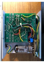
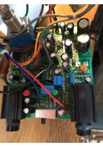
There are a few possible pain points here. If it's the threshold that's causing the problems, it could be the octo-coupler or maybe the side-chain (i.e. what the octo-coupler is reacting to). Could you post some images of the board?

I would maybe start by measuring the resistance of the LDR when it's both off and when there is signal passing through it. Then check if the LED is okay (resistance, diode check on a multimeter). The octo-coupler basically alters the gain of the whaterever is doing the compression - I don't know if that's the tube or a transistor or an opamp in this circuit. Something is probably going wrong there.

EDIT: Just found some images of the gutshots online. That's one tight build! If you could show some clear, high def photos of both sides of the board and some pictures that clearly show where the wires are going, that would be a great help.
 
If you haven't, try contacting Bob Bradshaw directly. He's a very chill personable guy in my couple on run ins with him. There's still a lot of his legacy gear bouncing around Nashville
bobcae@outook.com
 
Hi jwin615,

Thank you very much for the suggestion. I wrote to him before, but received an automated message. It was another e-mail address though. I just wrote him again, so I am crossing my fingers to receive some info this time.

Frankly speaking, the boost of the comp when the threshold is turned off (all the way counter-clockwise) is so beautiful, so even if I cannot fix the problem, I will still use it as a boost pedal!
Statement on the website said he was having Microsoft Outlook problems and to use that address.
Hopefully Bob helps you out.
 
Sorry I haven't replied! Nothing looks obviously out of order here. It's not immediately clear exactly how it all works without having one in front of me, or a schematic. There certainly is a lot going on. Can you follow traces? If so, do you have access to a signal tracer/oscilloscope? If also yes, you may be able to find out exactly where the unwanted distortion is coming from. Pay attention to the components around the vactrol (VTL5C4) and the threshold knob. You might have to measure a lot of different components. How familiar are you with troubleshooting methods like diagnosing diodes, transistors and the like?
 
Thank you very much... I am not familiar with troubleshooting methods unfortunately? I am good at soldering if I am told (or sometimes I can figure out) what component to change! :) The only tools I have are a decent multimeter and a good soldering station. I e-mailed Bob asking for the schematic. I will share it here if I receive it...

Best regards,

Alper

Sorry I haven't replied! Nothing looks obviously out of order here. It's not immediately clear exactly how it all works without having one in front of me, or a schematic. There certainly is a lot going on. Can you follow traces? If so, do you have access to a signal tracer/oscilloscope? If also yes, you may be able to find out exactly where the unwanted distortion is coming from. Pay attention to the components around the vactrol (VTL5C4) and the threshold knob. You might have to measure a lot of different components. How familiar are you with troubleshooting methods like diagnosing diodes, transistors and the like?
 
I am not familiar with troubleshooting methods unfortunately?
That's totally fair! This certainly looks like a challenging one to pin down, but with the schematic I fully believe that with enough trial and error, you'll be able to nail it. (y)
The only tools I have are a decent multimeter (...)
Does that have a diode check function? I believe that will be important to figure out what is going on.
 
My multimeter is a Fluke 15B, which has the diode check function. I will look into all individual components around the vactrol as you suggested and try to see if there is anything weird going on. In the meantime, I will be still waiting for the schematic from Bob. In the worst case scenario, I am planning to take out everything and trace the whole circuit; I think I can do that! :) Thanks, @mzy12.
 
Back
Top