Jbanks
Active member
Hi all,
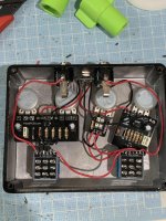
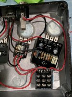
Im building a double booster that is half SHO and half Amentum (EQD Arrows). I’d like to have a tone stack PCB for mid boost as well.
I realized that my previous wiring up the tone stack after the Dboard of the Arrows meant that the Mid pot was always “on” regardless of the 3PDT for each boost respectively.
So I wired up the output of the PCB for the arrows to now go to the input of the tone stack PCB, then back into the output jack of the dboard and then out to the output jack from the daughter board.
However, now that the tone stack is “inside” the arrows switch circuit and can be controlled, I have a large loss of volume headroom. Now the boost on the arrows is barely noticeable volume wise.
Is there a way I can wire the tone stack PCB to be in the 3pdt circuit of the arrows boost without cutting out so much volume headroom?
thanks
James