Trembling Loon help

rozencratz

New member
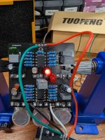
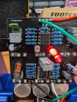
Hi everyone, this is my first non-kit build and unfortunately I'm unable to get a signal through the board. I've resoldered everything, confirmed the right components are in the right spot, it is powered, and I get a signal on bypass. But I'm totally stuck now for days trying to figure out what's wrong and where to go next.

I'd appreciate any insight someone can provide.

Thanks 1591.jpeg 1592.jpeg 1593.jpeg 1594.jpeg 1595.jpeg
 
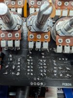
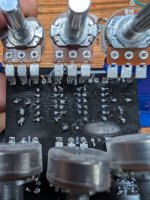
Take your time. A lot (almost all) of your solder joints look cold or wrong in some way. What kind of solder and soldering iron are you using, and did you have success with kits beforehand?

View attachment 105268
I did have success on the first try with my 2 kit builds. Using a YIHUA 939D+and 63/37 Rosin Core solder with 1.8% flux 0.8mm.
I'll try desoldering and rebuilding I guess and take some more time with the soldering.
 
Hi everyone, this is my first non-kit build and unfortunately I'm unable to get a signal through the board. I've resoldered everything, confirmed the right components are in the right spot, it is powered, and I get a signal on bypass. But I'm totally stuck now for days trying to figure out what's wrong and where to go next.

I'd appreciate any insight someone can provide.

ThanksView attachment 105259View attachment 105260View attachment 105261View attachment 105262View attachment 105263
I believe the LDR needs to be positioned near the LED and sealed up so no light leaks for testing.
 
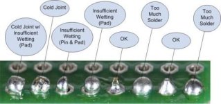
you can touch up the solder points without desoldering and doing them over. maybe set your iron just a little bit hotter than you have been doing, make sure the tip is clean. for the places with too much solder put the tip on that spot and melt the solder. make sure the tip is touching the metal contact on the board and the wire. the solder will reflow and some should come off on your tip when you remove it. clean the tip and move on to the next one. for cold-soldered joints the goal is to warm them enough for the solder to reflow to the shape of your "OK" joints marked above.

try fixing all of those solder points and the clean the board by spraying some isopropyl alcohol on it and brushing it with an old toothbrush or similar item. let the board dry and see if it helps you get sound through the board. getting your solder points solid and the board cleaned will at least go a long way toward making your trouble-shooting easier.
 
I’ve moved the LDR to face the LED2, I’ve removed LED 1 since it belongs on the outside of the enclosure. I’ve reflowed all solder and made it nicey-nice. Still nothing.
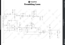
I built a make shift audio path tracer and get the signal at only 1 side of R18, 1 side of R5, and touching IC1 pin1. I get no signal at IC1 pin 2 and nothing at C8 or later.
Can someone please explain how this is possible and what I can do to fix it?
 

Attachments

  • IMG_0544.jpeg
    IMG_0544.jpeg
    258.8 KB · Views: 6
How are you audio probing this? What tools are you using? What you describe doesn’t make a lot of sense. You can’t have signal at the output of IC1 but not at the input.

One thing others have not mentioned: did you make sure all the components have the correct values? Did you measure them before installing? You can do a visual inspection and read the values now to at least verify that.
 
Back
Top