SOLVED Triangle Muffin problems..

Idroj

Active member
Hi everybody, this is my very first post here.

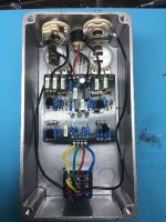
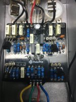
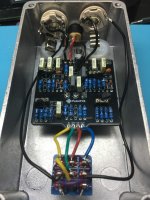
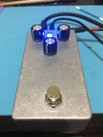
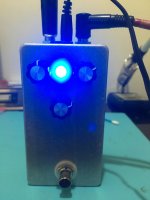
It is the Triangle version of the Muffin Fuzz, but with 2N5089 transistors and 1N4148 diodes. I must have looked at the The Fox's BOM by mistake, instead of Triangle, when ordering those parts. I read somewhere that those parts were interchangeable so I gave it a try... LED turns on and off, I get sound on bypass but nothing when on. Only a faint buzzing that gets interrupted when I touch the enclosure.

Any help would be greatly appreciated.

Thanks

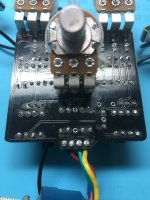
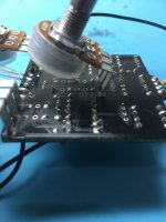
IMG_7702.jpg IMG_7704.jpg IMG_7706.jpg
 
The basics look good, didn’t check every component but on a quick glance nothing jumped out. The 2N5089s should be fine just a a little more gain than 2N5088 and the 1N4148s are basically better 1N914s so that’s fine. I gotta ask the easy question since everyone has done it, were you checking pedal with back off for the first time, and if yes did you plug the input Jack into the out put? I’ve done that more than once. If not, can you take pictures of the back side? Also can you take the DC bias voltage of all 4 transistors, collector base a emitter, just want to make sure the are right.
 
I believe I had the back on (cover on) when I first turn it on. I'm pretty sure I plugged the guitar jack into the stereo input and the amp jack into the mono output first, but not 100% sure.. Let me ask, if I had it backwards, or the back off could I have damaged anything? I wish I knew how to take the DC bias voltage of transistors... Is it pretty simple to do?

I will take it apart and snap some pics of the back.. Thanks!
 
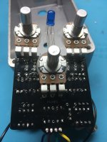
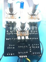
It looks like there is no solder on pins 1 and 2 of the tone pot from the back, they may be cold solder joints. Re-solder those points and check it. There is no problem with checking the pedal with the back off, its quite common for some people to test it for the first time this way, its also quite common for people who do this the plug the jacks in reversed (I'm Guilty!). There is no problem with that either. Believe it or not most problems arise from the build process, once you get the circuits working they are pretty robust. So re-solder pins 1 and 2 on the tone pot. and clean the board with IPA and a toothbrush, careful not to get the dirty alcohol in the pots. It will take a bit of scrubbing but all the flux goop needs to be removed.

DC bias readings are easy. If you have a multimeter, if not get one if you plan on building more pedals, the black lead will go to ground if you have clips, the jack sleeve is a good grounding point, turn multimeter on to DC Volts and carefully touch each lead of the transistor one at a time with the red lead. Record each reading. If your looking at the front of the circuit board, the collector is the right lead, the base is the middle lead and the emitter is the left lead. If you google 2N5089 datasheet. it will have the pin out for the transistor. Just take those readings, and post them. Oh yeah, when you take DC bias readings, the pedal has to be plugged in to power and on, but not necessarily plugged into amp or guitar.
 
Last edited:
Ok I will do that! See what happens.. I'll update, thanks!
Two questions:

1.- When cleaning with IPA and a toothbrush, what is the process, just dip the toothbrush on IPA, scrub and dry with a qtip or similar? Or pour a little IPA on the board? Can IPA damage components?

2.- I have a multimiter, it is one of those red cheap ones, not digital, range type.. I've only used it to check continuity and checking ohms on resistors. So to check the bias readings, put one leg on the pedal's in/out jack's sleeve, and touch each lead of the transistor with the multimiter on DCV, but on what range should I have it for these readings?

By the way, thanks so much for the help. I started building pedals a few months ago, built 3 pedal kits (from another seller) with no problems whatsoever, super fun. Later discovered and switched to pedalpcb and tayda, and this is the 3rd faulty pedal I build in a week.. I have a RAT and a BLUE BREAKER sitting in a drawer (I'll post them in the forum later if I can get this one going).. after hours and hours of troubleshooting attempts, decided to just quit and build a 3rd one, this MUFFIN, I just knew the 3rd one would work, well, here I am... I'm starting to think maybe it is some of the parts I selected.. maybe I should have built a few more complete kits before jumping into buying all the separate parts on my own..
 
To clean the board, read this (scroll down to figure 16):
 
Thanks I'll get this done this morning. At one point, I had all the pots backwards, I know, I need to slow down..
Once I get all the legs touched and the back clean, I'll try to take those measurements. With the multimeter on DCV, what is the appropriate range to measure DC bias voltage of all 4 transistors ? Mine is not digital..
 
Ok I will do that! See what happens.. I'll update, thanks!
Two questions:

1.- When cleaning with IPA and a toothbrush, what is the process, just dip the toothbrush on IPA, scrub and dry with a qtip or similar? Or pour a little IPA on the board? Can IPA damage components?

2.- I have a multimiter, it is one of those red cheap ones, not digital, range type.. I've only used it to check continuity and checking ohms on resistors. So to check the bias readings, put one leg on the pedal's in/out jack's sleeve, and touch each lead of the transistor with the multimiter on DCV, but on what range should I have it for these readings?

By the way, thanks so much for the help. I started building pedals a few months ago, built 3 pedal kits (from another seller) with no problems whatsoever, super fun. Later discovered and switched to pedalpcb and tayda, and this is the 3rd faulty pedal I build in a week.. I have a RAT and a BLUE BREAKER sitting in a drawer (I'll post them in the forum later if I can get this one going).. after hours and hours of troubleshooting attempts, decided to just quit and build a 3rd one, this MUFFIN, I just knew the 3rd one would work, well, here I am... I'm starting to think maybe it is some of the parts I selected.. maybe I should have built a few more complete kits before jumping into buying all the separate parts on my own..
1. When cleaning with IPA, the only components you need to be careful of are the pots. When cleaning the back side of the board, just make sure the pots are up and don't pour IPA on them. If cleaning front side of board, just a drop or two at a time with pots installed. As for dipping or pouring, its a personal preference really, I pour myself. Scrub with the toothbrush then clean, Q-tips work wonders to dry, but can leave cotton strands everywhere. Lately I've been wiping gently with an old t-shirt or a clean sock inside out, so the fuzzy side is wiping, and they work great. A little more robust than a Q-tip so start gently if you go this route and get comfortable with it.

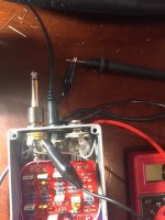
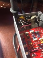
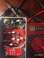
2. A multimeter is a multimeter, I have a cheap $7 red one for quick checks and it works great, I also have an auto-ranging one for more lengthy work. They both do the job, so what ever you have is fine. If you have jumpers with alligator clips, clip the black lead on to the sleeve of input or output jack, the are both big ground targets and easy to get to. Now you have both hands free to work. The voltages will be all 9V or less so set the range to cover that, most multi-meters have a 20Vdc range. `Below are pics on how to connect multimeter, the second one is good if still in the box. I also took the bias voltages of my Triangle Big Muff, Q2 collector looks weird, this is due to resistor R9 being removed.


IMG_3161.JPG IMG_3160.JPG IMG_3159.JPG

Transistor Bias Volts:
Q1 C=3.7V
B=.6V
E=.02V

Q2 C=1.32V
B=.71V
E=.1V

Q3 C=3.68V
B=.6V
E=.02V

Q4 C=3.96V
B=1.7V
E=1.22V
 
Re-soldered those legs, cleaned the back, aaaand it WORKS and SOUNDS beautifully! Thank you so much!!

Now, I have two other faulty ones I build prior to this one, a Blue Breaker and a Rat. I've never really used forums much.. should I post the pics here or start a new thread?

IMG_7709.jpg IMG_7710.jpg IMG_7712.jpg IMG_7713.jpg
 
Quick question: I just realized this build doesn't have a battery option. I have 9V battery clips, how could I add one? Where would I solder the + and - wires? Thanks!
 
Back
Top