True Bypass work?

That is quite possibly the most confusing true bypass set up I've ever seen.

I typically attach pins 1 and 8 aswell but that makes so much more sense than that one you posted.
1763097944452.png
 
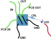
I also use that one (I think it's in all the PPCB docs too). The original PCB posted would have worked fine, the only comment I have is that the pins are usually "Input, pedal/board input, ground, LED, pedal/board output, output" in that order more or less, so you might want to stick with that yourself too. It's up to you of course, if you want to do it differently it's probably fine, but if you use some other variants from time to time it might be less confusing to do the same thing.
 
IMG_8604.jpeg

Here’s the PPCB one (with the PCB In grounded on bypass). Works, easy to tell what’s going on at a glance.
But if you want to reinvent the wheel in a way that makes more sense to you…🤷‍♀️
 
  • Like
Reactions: Nic
That is quite possibly the most confusing true bypass set up I've ever seen.

I typically attach pins 1 and 8 aswell but that makes so much more sense than that one you posted.
View attachment 106148
Pedalpcb is the same except link 1-8 to ground the pcb input in bypass.

Ori managed a scheme where both the pcb in and out are grounded, interesting. I’ve never encountered and issue with the pedalpcb way
 
Pedalpcb is the same except link 1-8 to ground the pcb input in bypass.

Ori managed a scheme where both the pcb in and out are grounded, interesting. I’ve never encountered and issue with the pedalpcb way
I don't think having the output hanging makes much of a difference since the input is grounded anyway. But maybe there could be some edge case where grounding the output might also be slightly better?
 
Back
Top