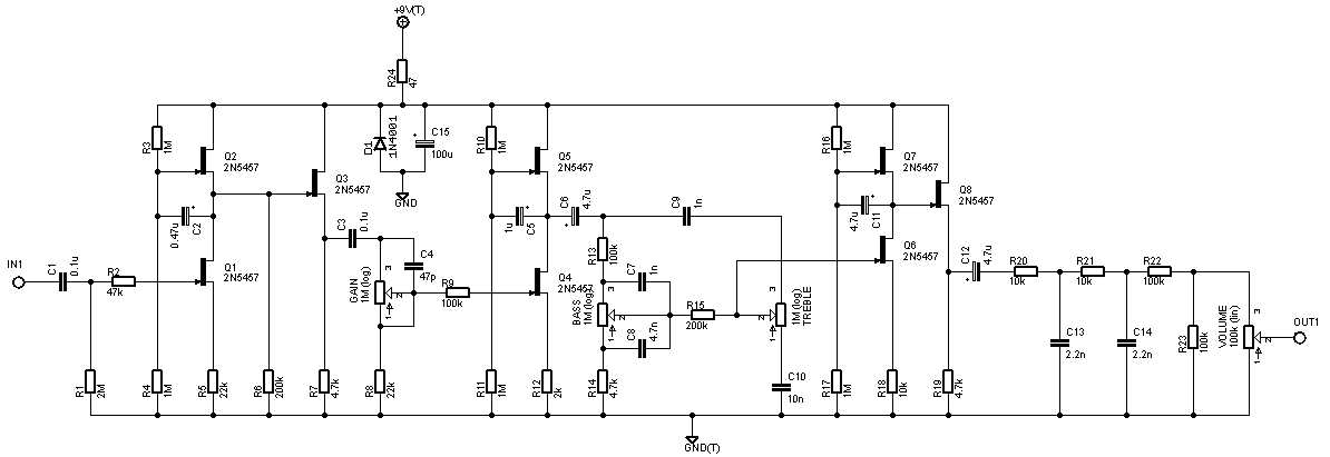
Tube amp schematic.. to FET pedal?

megatrav

Well-known member
I recently ordered the Lemon Rockerverb PCB from Guitar PCB Mania and I'm really excited to build it. Recently, I built a Sabbath from Pedalpcb. I was wondering, how does someone take a schematic of a tube amp and then convert the preamp section to a transistor based pedal?

I have wondered this for a while. It also raises other questions as I was looking into building some other higher gain pedals. Is there a particular reason that pedals like the BE-OD and Revv G2/3/4 don't use transistors to replicate their amps preamp? Is it more about the voicing and using standard clipping options that have been used is other pedals?

I hope what I am asking makes sense
 
. Is there a particular reason that pedals like the BE-OD and Revv G2/3/4 don't use transistors to replicate their amps preamp?

You get repeatable results with every pedal when using ICs. It's like plug and play. With JFET transistors (like J201, 2N5457, etc.) you have to bias each stage. Also you should take into account spread of the JFET parameters.

Taking schematic of a tube amp and replacing tubes with transistors while leaving rest of the circuit as is - it works (usually) but it's not a best way to get a good emulation of the original sound.
 
I've got the Lemon Rockverb as well, waiting its turn in the queue. I had it about a year before the build doc, so I got impatient and wound up tracing it and making my own schematic — literally a couple days later the build doc was released. 😸

Here's the links for the ROG:

From what I understand, sometimes some things need to be scaled down accordingly, too.
A transistor doesn't have the same requirements as a tube, so a direct swap of JFET for tube in a schematic isn't always feasible nor desirable. What components and values need changing? I don't know, it's been a while since I read up on it and even when I did I only had a vague understanding.

Also take a look at Bajaman's circuits. He does a lot of amp emulation but does it mostly with ICs.


Sometimes it doesn't matter which path you take, so long as you arrive at your destination.
Sometimes you just need to get there, other times it's more fun to take the scenic route.
 
You get repeatable results with every pedal when using ICs. It's like plug and play. With JFET transistors (like J201, 2N5457, etc.) you have to bias each stage. Also you should take into account spread of the JFET parameters.

Taking schematic of a tube amp and replacing tubes with transistors while leaving rest of the circuit as is - it works (usually) but it's not a best way to get a good emulation of the original sound.
This makes sense from an R&D perspective. Its easier to take something that already works and just spend time tweaking the voicing. It probably makes more sense when using a high gain circuit like the ones I mentioned as well.

I have always read that FET overdrives will typically have a better response (closer in feel to playing a tube amp) but as time goes on I think that definitely depends on the circuit. I know the BE-OD and Revv pedals sound huge
 
There's also a question - how close to the original tube preamp do you want to get with jfets or opamps? What's your goal? What are the assumptions and criteria? Matched frequency response and signal envelope?
Here's an example - comparison of the AMT P1 with Peavey 5150.


I know the BE-OD and Revv pedals sound huge

Yes, but do they sound identical to the originals? On the other hand - does it matter? :) They're so popular anyway
 
There's also a question - how close to the original tube preamp do you want to get with jfets or opamps? What's your goal? What are the assumptions and criteria? Matched frequency response and signal envelope?
Here's an example - comparison of the AMT P1 with Peavey 5150.


Yes, but do they sound identical to the originals? On the other hand - does it matter? :) They're so popular anyway
If I were designing a pedal that is suppose to be a preamp section of one of my amplifiers, then I would want it to have a similar frequency response, but I would also want the feel and compression to be similar.
I guess that doesn't have to be cascading FETs, if using an opamp or whatever will work just as well. I would say it might be better since its shown to work for Revv and Friedman.
I have no idea if they're close to the amps and yeah they sell a bunch. They're good pedals as well, so no, I guess it doesn't matter
 
So what woul it be? What preamp would you like to emulate?
I'm actually not sure. I was just curious how it's done.
There are a lot of amps that would be fun to emulate, but I also know that some "amp in a box" pedals are trying to recreate the entire amp's character rather than just the preamp.
 
I was curious how they take tubes running at high voltages and change it to transistors. Also, would one transistor be only one gain stage?
I know that a standard 12ax7 can be set up as 2 gain stages
 
Depends on the circuit design?

A lot of amp-sims use mu-amp configurations of the JFET, for instance a lot of Catalinbread's AIAB circuits, as well as other brands. This deviates from the one-JFET-per-tube concept, being more akin to one mu-amp per tube.

Here's the Cat'bread SFT (posted at Thermionic Studios):

CBread_SFTSchematic.png


Mu-amp > boost > mu-amp > EQ > mu-amp > boost


Ampeg SVT:

svtpream.gif

Looking at just Channel One, thinking of the tube stages and splits as "mu-amps" and boosts over-simplified:
"mu-amp" > tuboost > EQ > tuboost > "mu-amp" > tuboost-amp

So not identical topology, but extremely similar.
 
Something to consider is the filter values and impedance. Vacuum tubes are high output impedance devices. For solid state pedal circuits, which are lower impedance, you should use bigger caps and smaller resistors. The general rule is to multiply the cap values by 22 and divide the resistance values by 22.

The schematic posted above from Catalinbread just used the same values from the amp. It could be reconfigured, for example, with 50K pots instead of 1M. That would be a better fit for use with JFETs and reduce noise.
Thanks for that calc. Do the 2N5457s need to be matched?
 
Something to consider is the filter values and impedance. Vacuum tubes are high output impedance devices. For solid state pedal circuits, which are lower impedance, you should use bigger caps and smaller resistors. The general rule is to multiply the cap values by 22 and divide the resistance values by 22.

The schematic posted above from Catalinbread just used the same values from the amp. It could be reconfigured, for example, with 50K pots instead of 1M. That would be a better fit for use with JFETs and reduce noise.
Gold nuggets right there! 👆 Thanks for the education! 1625882093799.png
 
  • Like
Reactions: fig
Back
Top