Tube preamp project, how to test / breadboard?

ThomasMan

New member
Hi,

I'm writing because I'm planning on making a tube preamp pedal starting from a schematic I found, however it's my starting point with tubes (also thanks to @vigilante398 for the great 101 & 102 entry level guides :) ) at relatively high voltage and I would like to be as safe as possible, and regarding this it would be of a huge help to get some of your knowledge.

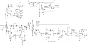
The schematic I'm looking at is this (not mine):
View attachment 65164

it's a ODS based preamp using 2 subminiature tubes. As you can see it runs via a 555 based SMPS (which should get between 150 and 200V). The guy that designed this is not reachable unfortunately, however he stated that the results were very nice.

My first big doubt is, I already have all of the components, but what is generally a safe way of testing/breadboarding it? I have read a lot of contrasting opinions in regards of high voltage breadboarding, some saying that the cheap solderless breadboards should work fine as long as keeping some distance between rows to prevent capacitance issue (however I don't feel very safe in doing so, no?), other saying there's no way they can handle 200 V.

What would be your way of testing the circuit before designing a proper PCB?
I though also at perf boards, but it also comes with some other draw backs.

Thanks a lot in case you can take the time to help me.

Best regards
 
I'm having trouble viewing your attachment, but does it by chance look anything like this?

Mac-Guffin-sch-010621.png

You can absolutely breadboard high voltage circuits. The metal contacts used in solderless breadboards is thicker than the traces used in PCBs, there's no issue regarding them being able to handle it. Leaving extra space between is of course a good idea, both for noise and for safety. Also make sure you keep your hands away from the circuit when it's powered up; it's fairly common to want to change things on a breadboard during testing, but with tube circuits you have to remember to wait until everything has discharged (10 seconds or so with a SMPS, obviously longer with a transformer/rectifier).

My method of testing things probably isn't what you want, because I actually treat PCBs as my breadboard. I'll do a little math and design something I think should work then order a PCB immediately, with the understanding that components on a PCB can be swapped as needed to tweak the sound to my liking. I only use a breadboard when I'm designing something weird that I'm not sure will work.
 
I'm having trouble viewing your attachment, but does it by chance look anything like this?

View attachment 65210

You can absolutely breadboard high voltage circuits. The metal contacts used in solderless breadboards is thicker than the traces used in PCBs, there's no issue regarding them being able to handle it. Leaving extra space between is of course a good idea, both for noise and for safety. Also make sure you keep your hands away from the circuit when it's powered up; it's fairly common to want to change things on a breadboard during testing, but with tube circuits you have to remember to wait until everything has discharged (10 seconds or so with a SMPS, obviously longer with a transformer/rectifier).

My method of testing things probably isn't what you want, because I actually treat PCBs as my breadboard. I'll do a little math and design something I think should work then order a PCB immediately, with the understanding that components on a PCB can be swapped as needed to tweak the sound to my liking. I only use a breadboard when I'm designing something weird that I'm not sure will work.
Thanks a lot for the answer! And yes! It's that one (not sure what happened with my attachment). Since you recognised it immediately, have you by any chance already gave it a shot?

Anyways, I understand your approach, but I guess it partially comes from your experience of knowing with pretty high confidence the presence (or absence) or a specific component and it's effect, and then playing around with values directly on the PCB, if I understood correctly.

I think I will try to give it a shot first with breadboarding, as I feel like the possibility of quickly changing/removing/adding components would also benefit the overall learning.

Just a small follow up, I know the output voltage of the SMPS depends on the duty cycling of the 555, however, does it still make sense to manually discharge the various capacitors (even the ones on the main circuit) or it's just overkill if I waited (e.g.) 1 minute from when I switched off the input?
Pretty sure that was a @jubal81 build, wasn't it? I haven't personally tried the circuit.

Discharging the caps manually is overkill if you're already waiting a minute after power is removed. They will discharge pretty quickly on their own, it's not like a typical tube amp.
 
Pretty sure that was a @jubal81 build, wasn't it? I haven't personally tried the circuit.

Discharging the caps manually is overkill if you're already waiting a minute after power is removed. They will discharge pretty quickly on their own, it's not like a typical tube amp.
Yes that is correct, it was his build :)

Thanks for the help, I feel a bit more confident now.
I will update on the results!
 
Hey @vigilante398, forgive me for bringing you up again but I'm facing a small doubt.
While waiting for the tubes to arrive I have assembled the breadboard completely, including the SMPS.

When testing (with a multimeter, no load) the SMPS I am noticing some strange behaviour: the output voltage reaches up to 370 V, down to 60 V minimum, with a non linear shape when adjusting the trimmer pot.

How can I verify that it is working correctly? It appears to NOT be working correctly as the voltage should be lower from what I understood.

I suspect that I don't have the right MOSFET. Besides obviously the correct voltage rating, are the Idss and RdsOn values crucial for the SMPS?

Thanks
 
Last edited:
Ok I ordered a bunch of https://www.mouser.se/ProductDetail/78-SIHA18N60E-E3 for Q3, and BC549CTA transistors for Q2 which I really hope would get the job done
🙏
😅
 
Hey @vigilante398, forgive me for bringing you up again but I'm facing a small doubt.
While waiting for the tubes to arrive I have assembled the breadboard completely, including the SMPS.

When testing (with a multimeter, no load) the SMPS I am noticing some strange behaviour: the output voltage reaches up to 370 V, down to 60 V minimum, with a non linear shape when adjusting the trimmer pot.

How can I verify that it is working correctly? It appears to NOT be working correctly as the voltage should be lower from what I understood.

I suspect that I don't have the right MOSFET. Besides obviously the correct voltage rating, are the Idss and RdsOn values crucial for the SMPS?

Thanks
What behavior were you expecting from the SMPS? 60V to 370V in a nonlinear sweep sounds correct to me.
 
What's the expected VC? Avoid breadboarding the power supply. Usually the contact resistence on the breadboard is too high for the current spikes you can find in switching supplies.
 
What behavior were you expecting from the SMPS? 60V to 370V in a nonlinear sweep sounds correct to me.
I was expecting less output voltage, when the project was first posted I remember the output voltage of the smps was said to be around 200V. 370V felt a bit too much by following more or less the same circuit.

Also by non linearity I also mean that there is a point in the trimmer resistor where a minimal change makes the output voltage go from 100 V to around 300 V. But maybe that's normal
All the pedal projects are designed to operate around 200V on the rail because that's what the resistors I chose set them at. The SMPS standalone board uses a trimpot to give you a wide range that you can tailor to your needs, so I didn't feel the need to limit the output voltage to 200V.

The non-linearity is to be expected, it's just the nature of NE555 as a controller. Some people have said using a resistor in series with a 1k pot instead of just the 5k pot makes it easier to dial in but limits the available range. But this is why I don't use trimpots to precisely dial in the voltage in pedal projects, it's difficult to get exactly what you want.

If you want it hard-set for 200V like the pedal projects, replace the 5k trimpot with a 4k7 resistor between pins 1/2 and a 560R resistor between pins 2/3.
Sorry for not answering, I appreciated your explanation.

I just received the tubes, so soon I will hopefully have a first sound test from the breadboard :)
 
Ok so, breadboard was assembled completely.. obviously it didn't work, as I only get a sort strong background noise (I connected the guitar directly in the input, as the output to a mixer).

I would have many questions, but perhaps the fundamental one in regards to debugging the issue is: looking at the circuit, at which points could I get some sound? For example, if I connect the mixer after the first tube, can I check that at least I get a sort of boosted signal? Same thinking after the tone stack for example?

Not sure if it's the right mindset, but I guess I could look at it section per section.
Assuming you're looking at the schematic I posted above, the first place you would see boosted audio signal would be on the node where C2 and R6 meet.
 
Assuming you're looking at the schematic I posted above, the first place you would see boosted audio signal would be on the node where C2 and R6 meet.
I just tested the output and I indeed get something between C2 and R6 (not very boosted, if boosted at all).
I then tested where C11 and R35 meet, right before the OD section. I also get sound there, significantly more boosted than the previous test, however there is something I can't really understand: all of the tone stack pots does not influence the output (even the gain knob for example), but even more strange is that I still get sound when I disconnect the gain pot completely (PS for simplicity I did not breadboard any switch, meaning that the circuit I have it's basically the state of the one in the schematic).

In that case (with the gain knob disconnected) there should be no influence from the guitar signal going into the grid of the second stage no?

One doubt I have also is if I did a mistake in using the same tube for the input and tone and the other tube for the two overdrive stages. I can see V1T1 in the input one and V1T2 after the tone stack. Not sure how to interpret that :)
 
Back
Top