Well That's One Way To Hide An IC

I really doubt that is more than 2 layers. the tell-tale would be via that don't connect to a trace on the other side of the PCB .
Well, either there’s a middle layer or he put some components on here that lead to… nowhere!

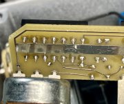
For instance, this pair of diodes is connected together, but… the trace at the top of em? Leads right under Pin 14 of the 40106 but doesn’t connect - on the front or back - to that Pin or anything else, it seems. The bottom snakes under the lm386 and leads right by Pins 2 & 8 - but again, doesn’t seem to connect to anything. No continuity with either of these traces to anything else on the board, seemingly.

There are a couple resistors that seem to have the same issue- not connected to anything on one end!
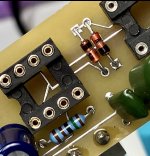
1780071389680.jpeg
 
they’re largely hidden under resistors and whatnot…
I just want to say that as a PCB designer I frequently hide my vias underneath components, mostly because I think it looks cleaner, but I admittedly also think about how much more fun it will be when someone tries to trace it.

If it looks like something doesn't connect anywhere though, try a continuity check with a multimeter and start poking around to see if it shows up.
 
I just want to say that as a PCB designer I frequently hide my vias underneath components, mostly because I think it looks cleaner, but I admittedly also think about how much more fun it will be when someone tries to trace it.

If it looks like something doesn't connect anywhere though, try a continuity check with a multimeter and start poking around to see if it shows up.
Ha, funny timing- see what I posted RIGHT before you a second ago!
 
Maybe there is a ground plane?
See if the floating pads have zero resistance to Vcc or ground.
There are a couple larger ground planes on the back, but I can’t see anything in between when I shine a very bright light behind it… Seems to be zero resistance to VCC and G on the “ghost traces” at the top and bottom of the diodes…
1780072298853.jpeg
 
@Robert whaddya do when you encounter blind vias while tracing? Give up? Cry?

I do most of my tracing with the DMM, not visually, so it really doesn't matter if the traces are hidden or how many layers are inside.

When all else fails and I just can't find a connection, I break this out and brush the board.

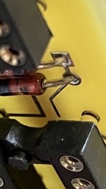
You might have to remove the socket to know for sure, but it wouldn't be the first time I saw dummy traces and components.

1780078374450.png
 
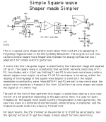
Looking at the TE circuits for something with a pair of diodes, there's the square wave shaper
1780079251160.gif
Maybe this is it, but with the Schmidt triggers and filter mixed in. Or was it established this is a single opamp/386.
Curious if one side of those diodes goes to one of the greenies attached to ground.
 
That trace under pin 14 could maybe go to a via in that "ground plane" and be filled with solder?
Looks to be solder flowed on it.
 
You might have to remove the socket to know for sure, but it wouldn't be the first time I saw dummy traces and components.
Huh, that’s pretty nifty…

That trace under pin 14 could maybe go to a via in that "ground plane" and be filled with solder?
Looks to be solder flowed on it.

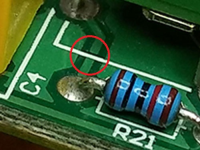
Here’s a clearer pic of the trace under Pin 14- seemingly doesn’t have continuity with anything… so strange

1780079848537.jpeg
 
I just can't see manufacturers wasting money on components that aren't actually somehow in-circuit. Maybe some paranoid smaller builder would do that, but not BOSS, MXR or DOD or other big names.


I'm going to start scoping out some bulk purchases, defective batches of diodes or resistors etc — RIGHT FROM THE COMPONENT-MANUFACTURER.

Then if I ever were to offer my stupid ideas commercially, I'll have the makings of red-herrings, wild-goose chases, and blind alley-cats...
 
Maybe some paranoid smaller builder would do that,
I mean, he did dremel away the IC markings even though this was highly derivitave of a known DIY circuit… Don’t get me wrong, I love what he did with it, but… if you’re gonna scrub ICs ya might also install some dummy diodes. They are part of Escobedo’s Simple Square Wave circuit, so that does muddy the waters

They don’t connect to anything though! I feel like I’m taking Crazy Pills here. :)

Regardless, I’m just gonna build a PWM and chop off the modulation. The extra two controls aren’t worth the trouble… guess he got me, folks.

Via con dios, Hiray…

See what I did there
 
Back
Top