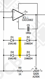
Theoretically not much. If one set of diodes is forward biased, the other is reverse biased with or without the bridge. There is a little junction capacitance added, but it's on the order of 4pF for 1n4148 and 15pF for 1N4004.
Paul Cochrane, creator of the original Timmy pedal claims there is a subtly audible difference. Did you end up breadboarding to see if you heard a difference? I don't hear one if I add/remove a jumper, but I'm in my 60s and my ears are kind of shot anyway.
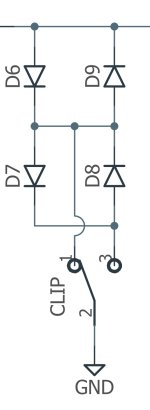
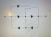
The first place saw this was in a Timmy/Timmy clone schematic where it allowed use of a SPDT with open center position to provide 2 options:
1) open - 2 diodes in each direction
2) short out a diode pair for 1 diode in each direction
3) switch in a single diode in one direction for asymmetrical clipping.
Search "Timmy clone Super-Freq schematic" for a drawing. There is also a bit of discussion in the various DIY forums and PaulC participated at times.

 so they guy that designed it is wrong? How’s that work?