SOLVED When your voltage divider just isn’t dividing

Diynot

Well-known member
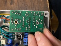
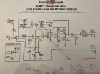
Ok Gang, I call upon your expertise and good graces. Building a headphone amp with an acetylene preamp into a ggg MXR headphone amp board. Acetylene works as advertised, but the amp just ain’t amping. I have checked values, reflowed joints, checked for solder bridges, and yes, even audio probed the SOB. Findings thus far is that the signal is dead at pin 6. Swapped ICs with same result. Voltage readings look to be off. With an 8.99v source, I have 8.3 at pin 3 input. Quick calculation using Vout= Vs x r2/(r1+r2) says it should be more like 4.45 coming from between r12 and r13. Unless I’m being a complete dumbass and that’s not a voltage divider. Here are the pics:

7D9482A3-411D-4AAA-82D8-3881B4A6508D.jpeg 930981F4-7DD3-4163-BDA8-F294BACEA67E.jpeg

3A144AF7-46DD-430C-85D4-1DBB30215EA7.jpeg
Hopefully one of you eagle eyed/technically savvy persons can help me out here
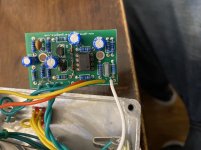
 
They were intact when I last checked, but it is totally possible I nicked it at some point in my trouble shooting. Thus far though, the signal isn’t even getting that far in the circuit.
 
@PedalPCB with the chip removed I am getting .81v in socket 3 and the expected 8.97 at socket 7. Either side of the 10m I get 8.97 on the divider side and .82v on the 1k side.
@spi I rechecked that transistor and it is fine (superficially), there was just some weird shininess on it.
 
Your meter is probably loading down the voltage on the opposite end of the 10M resistor, we'll look back at that later.

What we need to figure out is why R12/R13 isn't dividing the voltage... If the solder connections are good and both resistors measure around 10K the most likely cause would be a bad ground connection.

Where does your white wire connect?
 
It is connected to the cathode pad of one of the unused LED pads on the acetylene board. The acetylene is grounded to the negative on the power Jack and to the sleeve of the input Jack
 
The indictor LEDs at the bottom of the board (D3/D4) aren't grounded unless the corresponding footswitch is active.

The cathodes of the other two LEDs (D1/D2) aren't grounded at all.


Do you measure any DC voltage on the ground wire of the headphone amp PCB? That wire might need to be moved to another ground point.
(1/4" jack sleeve, DC jack, GND pad of the Acetylene PCB, etc)
 
Moved the ground to the output Jack and my voltage at pin 3 is now 4.45 as would expected. Audio still basically dying at pin 6 though. It’s attenuated not amplified even with the gain at 100%. May be time to pull out the breadboard
 
Flush with the hubris of having completed several builds sans sockets, I soldered the transistors here directly to the board. the orientation and parts were correct, but I may have baked one of them either on initial placement, or when I was reflowing my joints and realized, possibly a little late, that I had bumped the temp way up. That said, I placed sockets and replaced the trannies and I now have amplification! Huzzah! I now also have a horrific squeal, maybe grounding issues, that I need to track down. Thanks for all your help @PedalPCB
 
Doing this day job thing, but will audio probe when I get home. I THINK it may be the interaction between the acetylene and amp board, my suspicion is the grounding. I have an effects loop between the two and when Input is plugged into the return jack the amp is clean and if I run the send (via switched Jack) from the acetylene to an amp it’s fine
 
So the squealing came down to the power jack, either from the plug not being an exact fit, or the jack internals being loose. Some noted oddities with the build overall, I plugged a delay into the effects loop and ended up with some undesirable distortion. The other thing is that the acetylene doesn’t overdrive like expected, even with the boost on full. I have the bias set at ab 4v, but could probably turn up the input trimmer a bit
 
Back
Top