Where did I go wrong...

bokchoi1124

New member
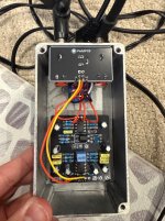
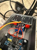
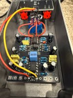
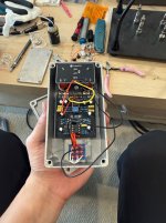
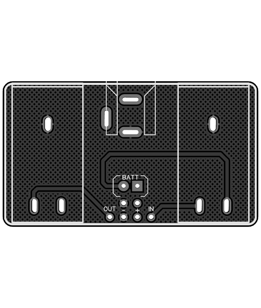
This is my first pedal build ever. I thought I followed all the instructions but it's clearly not working😅 When it's not engaged it's bypassed properly but when engaged, the LED doesn't turn on and the effect itself does not turn on/engage and so twisting the knobs does absolutely nothing. Anyone know where I can start troubleshooting from? I was making the Closed ciruit booster limiter. (Also i didn't space things properly so that's why my input outputs are on the bottom😅)
 

Attachments

  • IMG_5830.jpeg
    IMG_5830.jpeg
    959.8 KB · Views: 68
  • IMG_5831.jpeg
    IMG_5831.jpeg
    755.7 KB · Views: 66
  • IMG_5832.jpeg
    IMG_5832.jpeg
    816.7 KB · Views: 67
Gotcha! This sounds so awesome. If I change out ICs then will it make extremely different sounds based in what I choose?
Like @Fama already said, only in specific cases. Some folks like to try out different op amps in their drive circuits, for example, or if you've got a case where you have a vintage IC and want to compare it to a modern version (like in a Rat build). I've had cases where switching to a different one helped with ticking, or lowered noise, but it will all depend on the specific circuit.

For solder pumps, I've mostly seen two types (although I assume there are others):

The shit kind: https://www.amazon.com/Teenitor-Solder-Sucker-Desoldering-Removal/dp/B0739LXQ6N

And the good kind: https://www.amazon.com/ENGINEER-Engineer-Solder-Suction-SS-03/dp/B0D7Q293KV

Switching from the first type to the second type helped me a lot (even though I use a cheaper Aliexpress version of the second type). The small piece of silicone tube also helps since you can stick it right in there, so you can suck the solder out before it cools. Just need to clean the tube often or it gets filled with solder.

As someone who just switched to the good kind after a decade or so of the other kind, I can wholeheartedly agree. So much easier to get good suction.
 
Update: I finally desoldered the IC's switched them in their rotation and got everything wired up. Still no signal and the LED doesn't turn on haha. I may just order a new pcb and start over from square one.🤣 Thank you for all the help though. I guess I'll try again and see what happens next. This image of a well done one with definitely help
 
WAIT NEW UPDATE: I noticed when i was unplugging it from the power supply that as I was pulling out the plug the LED flickered! When the power cable touches the metal casing of the pedal it doesnt power properly! So now that I've taken it out of it's encasing it works! Does this mean I just need a bigger hole in my encasing?
 
Can we see a picture of the top (bottom?) of your pedal and how the DC jack connects?

Pedals are tip-negative, sleeve positive - so if your sleeve contacts the enclosure at all
you'll have a short and nothing will work because the enclosure is also at ground
(negative). This includes using a jack that has metal on the outside that touches the
enclosure in any way. (e.g. any of the nice-looking DC power jacks).
Ahh gotcha. I already took it out and am reorienting a couple things. But I am realizing the power io module isnt very flush because its a square and i only have the ability to drill a circle. Would covering the hole in electrical tape work? At this point looks are behind me haha i just want to get this thing working.
 
Last edited:
square and i only have the ability to drill a circle
There's a recent reddit thread about this very thing in /r/diypedals. ( )

Someone mentions they've 3d printed a covering plate - and you can also get a PCB made as a switchplate/faceplate.
There are some pinned threads on one of the forum links here that explain how to do that.
(https://forum.pedalpcb.com/threads/back-lit-faceplate-tutorial.27033/)

You could probably approximate this with a thin sheet of plastic and an exacto knife to cut out the rectangle for the power.

Electrical tape is fine, it won't look great but it'll work. You could probably gob it up with hot glue, too, but you'll
wanna be sure it works first!
 
That one is designed to mount inside the enclosure, the jack shouldn't protrude through the enclosure. If the jack is shorting to the enclosure you can enlarge the hole.
1775251550285.png


There is a flush mounted version, as well as a faceplate in the event you don't have any square drill bits.
powerio-flush-jpg.10909

 
That one is designed to mount inside the enclosure, the jack shouldn't protrude through the enclosure. If the jack is shorting to the enclosure you can enlarge the hole.
View attachment 114624


There is a flush mounted version, as well as a faceplate in the event you don't have any square drill bits.
powerio-flush-jpg.10909

OHHHH THATS WHAT THATS FOR I UNDERSTAND WHAT THESE FACE PLATES ARE FOR NOW!
 
Yep, but keep in mind they use a special version of the Power I/O module (the Flush mount version) with the DC jack positioned slightly higher so it protrudes through the enclosure.
 
Back
Top