jaminjimlp
New member
OK I got all the supplies to build the board and got it done forgot to get the charge pump IC and it came in and powered the board up and could not get the power to read right so I connected a LED to 3v connection and nothing connected it to 5v and it has a steady flash  after checking all the components orientation I found 1 cap (by the 3v reg closest to the 5v reg ) backwards... LOL so I changed it and still the same result. I am not a rookie at this stuff and I quadruple checked everything the cap backwards was a 4am thing LOL... I guess maybe I've fried the reg's and I even removed the charge pump IC and still no change. now the fuse that was used in the link was out of stock but Tayda had one with the same specs but different brand that's the only thing that is not exact as far as parts goes . so anyone have an idea were to start? Oh yeah with the CP IC in I get only 9v on the 18v taps.
One for the suggestion box:
I would like to see a LED power light and a Bypass \ Effect LED added to the board in a future revision, just my 2 cents.
after checking all the components orientation I found 1 cap (by the 3v reg closest to the 5v reg ) backwards... LOL so I changed it and still the same result. I am not a rookie at this stuff and I quadruple checked everything the cap backwards was a 4am thing LOL... I guess maybe I've fried the reg's and I even removed the charge pump IC and still no change. now the fuse that was used in the link was out of stock but Tayda had one with the same specs but different brand that's the only thing that is not exact as far as parts goes . so anyone have an idea were to start? Oh yeah with the CP IC in I get only 9v on the 18v taps.One for the suggestion box:
I would like to see a LED power light and a Bypass \ Effect LED added to the board in a future revision, just my 2 cents.
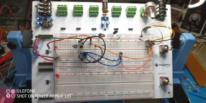


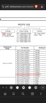
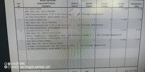
 so when I was looking for the regulators for the protoboard I figured
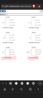
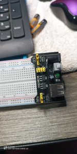
 hey let me get a couple for this other breadboard regulator and as I was looking through I saw there were some that handled more current so I ordered two of each of those as well as the ones that I'll put on the protoboard. So the other one I ordered that I put on the board as you can see is AZ1117CH2 and of course that one has the wrong pin out
  for the protoboard I figured I would go ahead and fess up and put it on here so maybe it will help somebody else at some other point might do something stupid like I did and in any case at least I figured it out.
 I searched around in my junk pile here and found the ones that were supposed to be in the board
 and since the one 5 volt one I put in there is working and it handles more current I'm just going to leave it but I have the correct ones to go in the 3.3 volt position and will be installing those today
  so all is well and boneheadville lol