
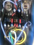
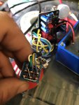
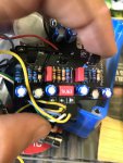
I’m having issues with my PCB I’ve looked at pictures of other wood pecker builds and I’m thinking I could have messed up some components. The c4 and c 10 if I’m not mistaken labeled 100u on the build doc. I’m using a 100uf 10v capacitor. However looking at the other builds the caps used in these areas look huge compared to mine. I’m having clean signal come through when bypassed. And nothing when engaged. I also have concerns about my level pot as one side of my pad secondary side has lifted while fixing cold solder joint. Any advice would be much appreciated. Sorry for the terrible photos I will add more if necessary
You are using an out of date browser. It may not display this or other websites correctly.
You should upgrade or use an alternative browser.
You should upgrade or use an alternative browser.
Woodpecker tremolo HELP
- Thread starter Jamesd324
- Start date
Betty Wont
Well-known member
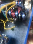
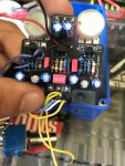
A 10v electro is a bad idea on a 9v effect. 1 16v minimum is recommended. We will need clear pictures of your switch and jack wiring. Also check the orientation and quality of your protection diode, it looks cooked. A lifted pad on the level pot could very well be your issue too. You might need to jump that pad to its neighbor in the circuit.
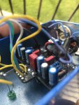
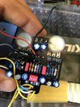
take everything out of the enclosure and take clear detailed pictures of each side of your board and all of the jacks (in/out/power). also a good photo of your wiring on the footswitch. while the parts are out of your enclosure, try it to see if it works.
Thanks for the help. I’m embarrassed about my soldering at home cause I work doing this J standard certification so I should have this in the bag. Go easy on me. I think what your seeing on the “cooked component is flux residue I am in the process of cleaning now. Any idea where that jumper might need to go?
Betty Wont
Well-known member
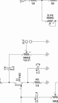
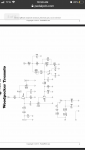
Look at the schematic and see what part/parts connect to the damaged potentiometer pin pad, then jumper directly from the pad to the corresponding pad on that/those part/parts.Thanks for the help. I’m embarrassed about my soldering at home cause I work doing this J standard certification so I should have this in the bag. Go easy on me. I think what your seeing on the “cooked component is flux residue I am in the process of cleaning now. Any idea where that jumper might need to go?
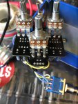

It’s the second leg lifted on the level bk100 so the jumper should go from leg to output. I’m not sure where that is. I’m not good with schematics once again thank you anyone willing to help me out. This community is always super resourceful.
Attachments
Okay I’ll be sure to do that thanksunrelated but one thing to do to make it easier to mount your pots in the enclosure --- use a pair of pliers and break off the small tab on the top side. otherwise the tab will keep the pot from mounting evenly against the inside of your enclosure.
Mcknib
Well-known member
The easiest thing to do if you think you've damaged the level pot pad is to snip your yellow wire from the out pad and solder it directly to the level pot middle lug 2 then your not trying to desolder anything from the pcb or 3PDT the wire's already there, that may well be what's causing your fault with no output, obviously make sure you physically solder your wire to the pot lug, the other end is already exactly where you want it to be.

As I say hopefully it'll just be an open circuit between the pot lug and circuit out and your nicely played guitar riff will be able to get out with the jumper ?
As I say hopefully it'll just be an open circuit between the pot lug and circuit out and your nicely played guitar riff will be able to get out with the jumper ?
Last edited:
I appreciate this I’m just now seeing it after desoldering all wires and re doing everything solder clean everything. On every wire. I added your exact suggestion just to see what would happen and to my surprise.. it fucking worked baby and we jammin now!!!! ??????????
