bengarland
Active member
I'm still learning this stuff, so I apologize if it's an obvious question:
When a pedal doesn't work after building it, what's the general step to figure out what's wrong?
Normally I would do a point-to-point continuity test from input to output to make sure the input signal is working its way around the board properly. Usually I'll find something amiss. But for some bigger builds this can take a lot of time. Is there something more basic that I can check to help locate the problem quicker?
Also, with some of the schematics I'm just confused about where the input signal is going. For example, I'm currently having a problem where the War Scythe isn't outputting any signal (here's the Build Doc). This seems like a "3-in-1" pedal and on the schematic there's IN1, IN2, and IN3... but there's actually only 1 physical input jack. Where do the actual input and output jacks signal go into the schematic? None of the 3 sections of the pedal are working so I think the problem might be near the input or output. And I'm not sure if the way this board is routed if it's an "all or nothing" signal (e.g. if one section had a bad solder joint somewhere, the other 2 sections won't work at all either?)
Any advice is appreciated. Again I'm mainly look for "here's how I would approach this" methodology / tricks from veteran pedal builders and not necessarily specific advice about this particular pedal. I know I can eventually figure this out, but it's a matter of whether I spend 4+ hours probing my way around the board or if there's some simpler and faster methodology I should be using instead. I feel like my soldering skills and general build quality are pretty good, so I get stumped when I put everything together slowly and carefully and it still doesn't work
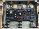
Here's a pic of the build -- I did the "Cleft" mod. I didn't put in the stomp indicator LEDs yet because I'm waiting on some bezels to arrive.
My available equipment:
Digital Signal Generator / Counter (new -- still learning to use)
RIGOL DS1054 O-scope (new -- still learning to use)
Standard Digital Multimeter
Thanks!

