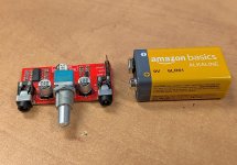
Headphone amp revisited. I was confident enough to order 25 boards right away, before any proper prototype. After all, it passsed DRC in Kicad, right, so it must be good? Nah. Somehow I misinterpreted the pinout of the 3.5mm jacks from the datasheet, so it ended up all screwed up. I had to cut traces, run little ugly wires, etc, just to make a single working unit. 24 out of 25 boards in the garbage, and back to the drawing board.
I mean, seriously, when you look at the metal bracket going around the front of the jacks, that's got to be ground, right? Right?
Nah. It's the tip. THE EFFIN' TIP!!!
You want to donate a couple of the boards to the "Edjamacate Feral Feline Fund-a-mentals", you go right ahead and send 'm my way. \
Appreciate also sending clear instructions on cutting those traces, running those wires...
You should start saving all your borked-boards, then make tile-mosaics from them, or beer coasters, or tile your bathroom...
^Actually they're perfectly usable if you use offboard 3.5mm jacks. But I don't want to keep them as I'm afraid I'll get them mixed up with the nearly identical fixed version, currently brewing at JLCPCB. You know what? I can donate a few of the fixed boards once I get them. It's easier than to explain the many cuts and fixes that need to be made to the bad boards.
Pro tip: first time I'm using this op amp, TLV910x. It's a lower cost, lower voltage cousin of OPAx990. Notable features: high current drive (80mA, and I use 2 in parallel per channel), and really low idle current (120 uA). Works down to 2.7V! Coin cell operation possible. Low Pwr'R'Us. Not exactly audiophile grade, but certainly good enough for the job.
In that other thread I mentioned I'd been messing with some stuff on the breadboard, but I didn't find it interesting enough (or sounding good enough) to share. Here's a little schematic of something I was messing with yesterday. It's literally on the workbench.
A long time ago I had this idea for a sort of fuzzstortion after seeing one of the weird EHX muff fuzz schematics where it was a dual op amp with clipping diodes. I didn't get it working on the breadboard so I came up with my own version. It's loud! It sounds pretty damned good, cleans up pretty well too. I'm not sure how interactive it would be with buffered pedals in front of it or after it because it's only on the breadboard by itself.
I think if I change R10 and C9 to 10k and 1nf it might help control the volume a little better. Haven't messed with it yet, though.
Still getting the new PCB mill set up and dialed in, last night I spent some time figuring out the process for 2-layer boards. I haven't soldered it up yet because frankly I don't need the board, but very pleased with the results. The only issue I'm finding is that the software doesn't like slot holes, so I'm going to have to stack my circular holes to make slots like you used to have to do at OSH.
I did the full rubout on the top layer which slowed things down, but this was maybe 45 minutes start to finish. The machine has auto tool-changing which speeds up the process a lot, and the camera with fiducial recognition makes alignment after flipping the material over super easy.
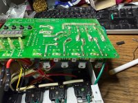
Well, I played it for a whopping 15 minutes before taking it all apart. Looks like a more than 2-layer board, with parts on both sides. It would probably take another pandemic for me to get bored enough to attempt tracing this for science
OK, so here's one of my basement workbenches, just not my electronics bench.
I just completed setting up a really solid woodworking workbench w/ a proper wood vise + bench dogs.
The workbench is from Global Industrial, bought on a major sale.
Solid hardwood top, with strong metal legs - will support more than 2 tons...
I modified it by adding the bench dog holes, additional leg stabilization, and properly finished the birch top.
For the vise, I bought the metal parts, but built the wood jaws & the mount.
And I put a nice layer of non-marring 1/16" silicone rubber on both wood jaw faces.
It came out really sweet.
had a glance, oh yeah…
this is pretty interesting..
how about that asymmetrical clipping method…
anyway so last night i was sitting on the couch, and suddenly it hit me - i gotta breadboard this thing right now.
picked the parts out, and plonked away at it on the coffee table.
nek minut it’s past 1am and i've 'finished it'. (of course there were errors)
- subbed the MC33178 with an RC4558 for IC1 and LF353 for IC2.
- attempted to sub this 2SK209 with a J201 but it didn't work (because im an idiot* lol)
so i subbed it with a 2N5089. (*i've just realized this morning while typing this out that i assumed an incorrect pinout)
eh it's just a buffer.
so after about half an hour of chasing and resolving my errors, i got it running properly.
nek minut, its 2am, i really should be in bed but im all perked up from anticipation, but there's no way i can fire up an amp.
so i booted up the DAW and ran it into a clean amp + IRs (Mesa 4x12).
ok.
so i was pretty skeptical about this thing.
but i was wrong.
while it's really not ideal to form any kind of an opinion in a scenario like this with distortion pedals (to me, they often sound pretty crappy into a DAW), well, given what I've heard through this setup (exact same patch) previously, this circuit actually sounds really fucken good.
the SLO pedal, suhr riot, RAT, aionfx ember distortion (tight metal), all sounded awful tested this way.
but this one actually sounds quite pleasant here. it's crunchy. the high end content isn't harsh. the decay is just the right amount of smooth. fuck yeah.
gain, tone and volume controls: - does pretty much exactly what you would expect.
the sensitivity control is interesting. seems like it behaves like a power amp saturation / thickener sorta thing.
so far so good, keen to see how it goes through a real amp tonight.
might even record it with the SM57 etc.
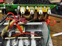
This came the other day. It is a great sounding amp with 2 issues. Noisy effects loop and a quick to get super loud master volume. I’m hoping to fix both. The PRS quality control seems pretty bad on this and some of the design choices are kind of baffling. It came not working as one of the transformer wires was not properly soldered but easy fix and it started up.
I did the full rubout on the top layer which slowed things down, but this was maybe 45 minutes start to finish. The machine has auto tool-changing which speeds up the process a lot, and the camera with fiducial recognition makes alignment after flipping the material over super easy.
Well, that's quite a production time, considering that you have ready-made holes. Using UV photo resist I can make a double-sided board in about an hour. Including exposure, curing the film, etching, maybe drilling. Soldermask not included. In 2 - 2.5 hours I have a complete board with holes and a description layer.
Well, that's quite a production time, considering that you have ready-made holes. Using UV photo resist I can make a double-sided board in about an hour. Including exposure, curing the film, etching, maybe drilling. Soldermask not included. In 2 - 2.5 hours I have a complete board with holes and a description layer.
Yeah hand drilling is definitely the worst part of etching. I still need to try out a soldermask, I've never actually done one on a board I've made. Is it as easy as the people selling the stuff try to make it sound?


") :
:
")


