SOLVED Aion Gale No Bypass Signal

joelorigo

Well-known member
This is a replica of Schaffer-Vega Diversity System in a pedal from Aion Electronics.

There is no bypass signal. The LED doesn't light up when activated. When the pedal is activated signal passes through - I can verify this because turning the knobs change the sound (the volume make it louder, etc.)

IMG_5011.JPG
 
Yes you need to ground both jacks so jumper the in and out jack sleeves together and then run a wire from the out jack sleeve to the ground pad on the bottom right, then jumper a wire from any ground pad left or right doesn't matter to 3PDT lug 5

As I said previously If the n.c. pad has continuity with ground use that to ground lug 5 to save you putting 2 wires in one ground pad
 
Last edited:
As for the LED, if I understand correctly, I connect the Cathode lead to footswitch lug 4 and attach the resistor from the breakout board to the Anode lead then connect that to the +V pad. So the +V pad will have 2 things connected.
 
Yep that's right if you look at this pic of my installed 3PDT you'll see I just soldered my resistor to the LED anode and tacked it onto the top of my +9v all I did was put a little solder on the resistor and melt it onto the top of my 9v solder joint

It doesn't actually matter which side of the LED you solder your CLR resistor to you can put it on the cathode if you want

20200922_211359.jpg
 
I did all the above. There was no continuity between the NC pad and any GND pad so I did a wire from lug 5 to the right GND pad.

Based on a previous comment I am not worrying about the diode and cap that was on the breakout board as I will be using a Voodoo Lab Pedal Power 2 when I use this.

However, now this has the opposite situation as the beginning of this thread. There IS signal on bypass mode but NOT any signal in effect mode. The LED does come on in effect mode!
 

Attachments

  • IMG_5081.JPG
    IMG_5081.JPG
    384.2 KB · Views: 13
Last edited:
First thing to check is have you got the right voltage on the right pins of your ICs. If you are not sure measure the voltages and post them here. The next step would be to use an audio probe to see where the signal is being lost.
 
Check anything you've changed wiring etc

If it was working before you removed the breakout board and now isn't I'd check everything you've done especially your pcb in and out connections

Reading your initial post I wasn't sure if it had worked 100% in effects mode from your description but if it was, there's a good chance it'll be something you've changed or moved

Yes it worked only I’m the effects mode at the beginning of this post. All the knobs changed the sound in some way.

What exactly should I do to “check” the things that were changed?
 
If you know the board works, the the problem is in the off board wiring. You changed power wiring, so make sure you are getting 9V (or close to) at the right places on the board. You changed the bypass wiring, so with the power off, and the switch in "effect on" position, trace through for continuity from the tip of the input jack, to the switch, and then through the switch and out to the board, then trace from the board out, through the switch, and to the tip of the output jack. If any of those don't have continuity, then that will be why you can't hear anything.
 
Check for continuity between the input and output ground terminals on the PCB. The picture shows the front ground plane is separated, if it truly is then you may not have a ground on the output side
 

Attachments

  • gale-booster-limiter-pcb.jpg
    gale-booster-limiter-pcb.jpg
    338.4 KB · Views: 8
First time visit to this thread.
Congrats to all the Members trying to make this Pedal fire up
Just curious, was a question about Momentary vs Latched 3PDT ever discussed in this Build ?
 
Basically you're looking to do all the continuity checks you did before

Stick your probe in the screwhole probe all your grounds and so on as you did at the beginning

Use the info you've got ie LED lights so that's got a ground connection bypass works so jacks are grounded and tips carry signal

Getting bypassed signal just tells you they're grounded and carry signal it doesn't tell you they're wired to the correct side the in could still be wired to the out you'd still get bypass signal if they were the wrong way around or if you put your in cable to your out jack accidentally with the enclosure the wrong way up, but you wouldn't get effect signal

Everyone has pointed out good things to check

music6000 makes a very good point hopefully that wasn't your problem all along
 
Just curious, was a question about Momentary vs Latched 3PDT ever discussed in this Build ?

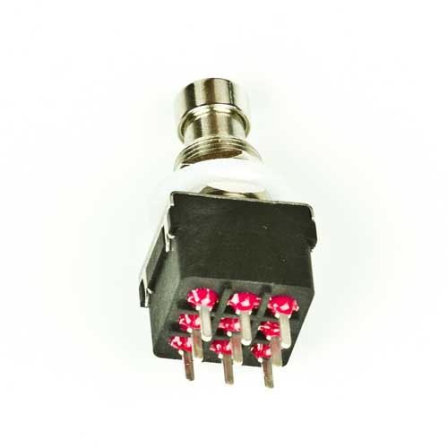
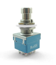
Im curious as to what this means. Using a momentary instead of a latched switch by accident? I'm pretty sure the previous one was not a momentary one as a have used the same ones before. As I mentioned earlier I had one of these that had a problem of one of the plates inside being off kilter. I think they were these:


And the one I'm using now is this one, which I have been using recently:

 
The one you're using is ok

If you used a momentary 3PDT one side would only be active if you kept your foot on it

There's normally open (NO) and normally closed (NC) types, on a 3PDT I think one throw would be normally open the other normally closed so you'd have one side always connected to the middle common row until you depressed and kept your foot on the stomp switch were it would throw it over to the other one

They're used for things like delay feedback for example where you'd only want a temporary change and as soon as you take your foot off, it would switch back to the normal setting
 
Back
Top